This User Manual documents Software version V2.00.100
Copyright © 2012-2023 FireBrick Ltd.
Table of Contents
- Preface
- 1. Introduction
- 2. Getting Started
- 3. Configuration
- 4. System Administration
- 5. Event Logging
- 6. Interfaces and Subnets
- 7. Session Handling
- 8. Routing
- 9. Profiles
- 10. Traffic Shaping
- 11. PPPoE
- 12. MQTT
- 13. Tunnels
- 13.1. IPsec (IP Security)
- 13.1.1. Introduction
- 13.1.2. Setting up IPsec connections
- 13.1.3. Using EAP with IPsec/IKE
- 13.1.4. Using certificates with IPsec/IKE
- 13.1.5. Choice of algorithms
- 13.1.6. NAT Traversal
- 13.1.7. Configuring a Road Warrior server
- 13.1.8. Connecting to non-FireBrick devices
- 13.2. FB105 tunnels
- 13.3. L2TP tunnelling
- 13.4. Ether tunnelling
- 14. USB Port
- 15. System Services
- 16. Network Diagnostic Tools
- 17. VRRP
- 18. VoIP
- 18.1. What is VoIP?
- 18.2. Registration and Proxies
- 18.3. Home/office phone system
- 18.4. Network Address Translation
- 18.5. Number plan
- 18.6. Telephone handsets
- 18.7. VoIP call carriers
- 18.8. Hunt groups
- 18.9. Directory
- 18.10. Call pickup/steal
- 18.11. Busy lamp field
- 18.12. Using RADIUS
- 18.13. Call recording
- 18.14. Voicemail and IVR services
- 18.15. Call Data Records
- 18.16. Technical details
- 18.17. Custom tones
- 19. BGP
- 19.1. What is BGP?
- 19.2. BGP Setup
- 19.2.1. Overview
- 19.2.2. Standards
- 19.2.3. Simple example setup
- 19.2.4. Peer type
- 19.2.5. Route filtering
- 19.2.6. Well known community tags
- 19.2.7. Announcing black hole routes
- 19.2.8. Grey holes
- 19.2.9. Announcing dead end routes
- 19.2.10. Bad optional path attributes
- 19.2.11. <network> element
- 19.2.12. <route>, <subnet> and other elements
- 19.2.13. Route feasibility testing
- 19.2.14. Status
- 19.2.15. Diagnostics
- 19.2.16. Router startup and shutdown
- 19.2.17. TTL security
- 20. OSPF
- 21. Command Line Interface
- A. Factory Reset Procedure
- B. CIDR and CIDR Notation
- C. MAC Addresses usage
- D. Scripted access
- E. VLANs : A primer
- F. Supported L2TP Attribute/Value Pairs
- F.1. Start-Control-Connection-Request
- F.2. Start-Control-Connection-Reply
- F.3. Start-Control-Connection-Connected
- F.4. Stop-Control-Connection-Notification
- F.5. Hello
- F.6. Incoming-Call-Request
- F.7. Incoming-Call-Reply
- F.8. Incoming-Call-Connected
- F.9. Outgoing-Call-Request
- F.10. Outgoing-Call-Reply
- F.11. Outgoing-Call-Connected
- F.12. Call-Disconnect-Notify
- F.13. WAN-Error-Notify
- F.14. Set-Link-Info
- F.15. Notes
- G. Supported RADIUS Attribute/Value Pairs for L2TP operation
- H. Supported RADIUS Attribute/Value Pairs for VoIP operation
- I. FireBrick specific SNMP objects
- I.1. Conventions
- I.2. Firebrick-specific structures for BGP
- I.3. Firebrick-specific structures for IPSec
- I.4. Firebrick-specific structures for L2TP
- I.5. Firebrick-specific structures for VoIP/SIP
- I.6. Firebrick CPU usage
- I.7. Firebrick system stats
- I.8. Monitoring for general system features
- I.9. System wide status
- J. Command line reference
- J.1. General commands
- J.1.1. Trace off
- J.1.2. Trace on
- J.1.3. Uptime
- J.1.4. General status
- J.1.5. Memory usage
- J.1.6. Process/task usage
- J.1.7. Login
- J.1.8. Logout
- J.1.9. See XML configuration
- J.1.10. Load XML configuration
- J.1.11. Show profile status
- J.1.12. Enable profile control switch
- J.1.13. Disable profile control switch
- J.1.14. Show RADIUS servers
- J.1.15. Show DNS resolvers
- J.2. Networking commands
- J.2.1. Subnets
- J.2.2. Renegotiate DHCP for a subnet
- J.2.3. Ping and trace
- J.2.4. Show a route from the routing table
- J.2.5. List routes
- J.2.6. List routing next hops
- J.2.7. See DHCP allocations
- J.2.8. Clear DHCP allocations
- J.2.9. Lock DHCP allocations
- J.2.10. Unlock DHCP allocations
- J.2.11. Name DHCP allocations
- J.2.12. Show ARP/ND status
- J.2.13. Show VRRP status
- J.2.14. Send Wake-on-LAN packet
- J.3. Firewalling commands
- J.4. USB/dongle commands
- J.5. Logging commands
- J.6. BGP commands
- J.7. OSPF commands
- J.8. PPPoE commands
- J.9. L2TP commands
- J.10. VoIP commands
- J.11. Advanced commands
- K. Constant Quality Monitoring - technical details
- L. Hashed passwords
- M. Configuration Objects
- M.1. Top level
- M.2. Objects
- M.2.1. system: System settings
- M.2.2. link: Web links
- M.2.3. routing-table: Default source IP for services using a given table
- M.2.4. user: Admin users
- M.2.5. eap: User access controlled by EAP
- M.2.6. log: Log target controls
- M.2.7. log-syslog: Syslog logger settings
- M.2.8. log-email: Email logger settings
- M.2.9. services: System services
- M.2.10. http-service: Web service settings
- M.2.11. dns-service: DNS service settings
- M.2.12. dns-host: Fixed local DNS host settings
- M.2.13. dns-block: Fixed local DNS blocks
- M.2.14. radius-service: RADIUS service definition
- M.2.15. radius-service-match: Matching rules for RADIUS service
- M.2.16. radius-server: RADIUS server settings
- M.2.17. mqtt-service: MQTT
- M.2.18. mqtts-config: Secure MQTTS service
- M.2.19. mqtt-config: Insecure MQTT service
- M.2.20. mqtt-external: External MQTT/MQTTS connection
- M.2.21. mqtt-map: MQTT message mapping
- M.2.22. telnet-service: Telnet service settings
- M.2.23. snmp-service: SNMP service settings
- M.2.24. time-service: System time server settings
- M.2.25. ethernet: Physical port controls
- M.2.26. sampling: Packet sampling configuration
- M.2.27. portdef: Port grouping and naming
- M.2.28. interface: Port-group/VLAN interface settings
- M.2.29. subnet: Subnet settings
- M.2.30. subnet-template: Subnet option templates for RA
- M.2.31. vrrp: VRRP settings
- M.2.32. dhcps: DHCP server settings
- M.2.33. dhcp-attr-hex: DHCP server attributes (hex)
- M.2.34. dhcp-attr-string: DHCP server attributes (string)
- M.2.35. dhcp-attr-number: DHCP server attributes (numeric)
- M.2.36. dhcp-attr-ip: DHCP server attributes (IP)
- M.2.37. pppoe: PPPoE settings
- M.2.38. ppp-route: PPP routes
- M.2.39. usb: USB 3G/dongle settings
- M.2.40. dongle: 3G/dongle settings
- M.2.41. route: Static routes
- M.2.42. network: Locally originated networks
- M.2.43. blackhole: Dead end networks
- M.2.44. loopback: Locally originated networks
- M.2.45. ospf: Overall OSPF settings
- M.2.46. namedbgpmap: Mapping and filtering rules of BGP prefixes
- M.2.47. bgprule: Individual mapping/filtering rule
- M.2.48. bgp: Overall BGP settings
- M.2.49. bgppeer: BGP peer definitions
- M.2.50. bgpmap: Mapping and filtering rules of BGP prefixes
- M.2.51. cqm: Constant Quality Monitoring settings
- M.2.52. l2tp: L2TP settings
- M.2.53. l2tp-outgoing: L2TP settings for outgoing L2TP connections
- M.2.54. l2tp-incoming: L2TP settings for incoming L2TP connections
- M.2.55. l2tp-relay: Relay and local authentication rules for L2TP
- M.2.56. fb105: FB105 tunnel definition
- M.2.57. fb105-route: FB105 routes
- M.2.58. ipsec-ike: IPsec configuration (IKEv2)
- M.2.59. ike-connection: connection configuration
- M.2.60. ipsec-route: IPsec tunnel routes
- M.2.61. ike-roaming: IKE roaming IP pools
- M.2.62. ike-proposal: IKE security proposal
- M.2.63. ipsec-proposal: IPsec AH/ESP proposal
- M.2.64. ipsec-manual: peer configuration
- M.2.65. ping: Ping/graph definition
- M.2.66. profile: Control profile
- M.2.67. profile-date: Test passes if within any of the time ranges specified
- M.2.68. profile-time: Test passes if within any of the date/time ranges specified
- M.2.69. profile-ping: Test passes if any addresses are pingable
- M.2.70. shaper: Traffic shaper
- M.2.71. shaper-override: Traffic shaper override based on profile
- M.2.72. ip-group: IP Group
- M.2.73. route-override: Routing override rules
- M.2.74. session-route-rule: Routing override rule
- M.2.75. session-route-share: Route override load sharing
- M.2.76. rule-set: Firewall/mapping rule set
- M.2.77. session-rule: Firewall rules
- M.2.78. session-share: Firewall load sharing
- M.2.79. voip: Voice over IP config
- M.2.80. carrier: VoIP carrier details
- M.2.81. telephone: VoIP telephone authentication user details
- M.2.82. tone: Tone definitions
- M.2.83. ringgroup: Ring groups
- M.2.84. directory: Directory entry
- M.2.85. etun: Ether tunnel
- M.2.86. dhcp-relay: DHCP server settings for remote / relayed requests
- M.3. Data types
- M.3.1. user-level: User login level
- M.3.2. ppp-dump: PPP dump format
- M.3.3. autoloadtype: Type of s/w auto load
- M.3.4. config-access: Type of access user has to config
- M.3.5. eap-subsystem: Subsystem with EAP access control
- M.3.6. eap-method: EAP access method
- M.3.7. syslog-severity: Syslog severity
- M.3.8. syslog-facility: Syslog facility
- M.3.9. http-mode: HTTP/HTTPS security mode
- M.3.10. radiuspriority: Options for controlling platform RADIUS response priority tagging
- M.3.11. radiustype: Type of RADIUS server
- M.3.12. mqtt-brokers: Select MQTT brokers
- M.3.13. month: Month name (3 letter)
- M.3.14. day: Day name (3 letter)
- M.3.15. port: Physical port
- M.3.16. Crossover: Crossover configuration
- M.3.17. LinkSpeed: Physical port speed
- M.3.18. LinkDuplex: Physical port duplex setting
- M.3.19. LinkFlow: Physical port flow control setting
- M.3.20. LinkClock: Physical port Gigabit clock master/slave setting
- M.3.21. LinkLED: LED settings
- M.3.22. LinkPower: PHY power saving options
- M.3.23. LinkFault: Link fault type to send
- M.3.24. sampling-protocol: Sampling protocol
- M.3.25. trunk-mode: Trunk port mode
- M.3.26. ramode: IPv6 route announce level
- M.3.27. bgpmode: BGP announcement mode
- M.3.28. sampling-mode: Sampling mode
- M.3.29. sfoption: Source filter option
- M.3.30. pppoe-mode: Type of PPPoE connection
- M.3.31. pppoe-calling: Additional prefix on PPPoE calling ID
- M.3.32. pdp-context-type: Type of IP connection
- M.3.33. ipsec-type: IPsec encapsulation type
- M.3.34. ipsec-auth-algorithm: IPsec authentication algorithm
- M.3.35. ipsec-crypt-algorithm: IPsec encryption algorithm
- M.3.36. peertype: BGP peer type
- M.3.37. radius-nas: NAS IP to report
- M.3.38. ike-authmethod: authentication method
- M.3.39. ike-mode: connection setup mode
- M.3.40. ike-PRF: IKE Pseudo-Random Function
- M.3.41. ike-DH: IKE Diffie-Hellman group
- M.3.42. ike-ESN: IKE Sequence Number support
- M.3.43. ipsec-encapsulation: Manually keyed IPsec encapsulation mode
- M.3.44. switch: Profile manual setting
- M.3.45. dynamic-graph: Type of dynamic graph
- M.3.46. firewall-action: Firewall action
- M.3.47. privacy-type: Privacy tag to use for withheld
- M.3.48. voip-format: Number presentation format
- M.3.49. uknumberformat: Number formatting option
- M.3.50. recordoption: Recording option
- M.3.51. voip-screen: Call screen setting
- M.3.52. ring-group-order: Order of ring
- M.3.53. ring-group-type: Type of ring when one call in queue
- M.3.54. voip-screen-set: Directory screen setting
- M.3.55. record-beep-option: Record beep option
- M.4. Basic types
- Index
List of Figures
- 2.1. Initial web page in factory reset state
- 2.2. Setup Wizard
- 3.1. Icons for configuration categories
- 3.2. The "Setup" category
- 3.3. Editing an "Interface" object
- 3.4. Show hidden attributes
- 3.5. Attribute definitions
- 3.6. Navigation controls
- 4.1. Setting up a new user
- 4.2. Software upgrade available notification
- 4.3. Manual Software upload
- 7.1. Example sessions created by drop and reject actions
- 7.2. Processing flow chart for rule-sets and session-rules
- C.1. Product label showing MAC address range
List of Tables
- 2.1. IP addresses for computer
- 2.2. IP addresses to access the FireBrick
- 2.3. IP addresses to access the FireBrick
- 3.1. Special character sequences
- 4.1. User login levels
- 4.2. Configuration access levels
- 4.3. General administrative details attributes
- 4.4. Attributes controlling auto-upgrades
- 4.5. Status LED indications
- 5.1. Logging attributes
- 5.2. System-Event Logging attributes
- 6.1. Port LED functions
- 6.2. Example modified Port LED functions
- 7.1. Default timeouts for session tracking
- 7.2. Action attribute values
- 8.1. Example route targets
- 13.1. IPsec algorithm key lengths
- 13.2. IKE / IPsec algorithm proposals
- 15.1. List of system services
- 15.2. List of system services
- 16.1. Packet dump parameters
- 16.2. Packet types that can be captured
- 18.1. Ring Type
- 18.2. Ring Order
- 18.3. Access-Accept
- 18.4. Default tones
- 19.1. Peer types
- 19.2. Communities
- 19.3. Network attributes
- 20.1. OSPF config attributes
- C.1. DHCP client names used
- D.1. Special URLs
- F.1. SCCRQ
- F.2. SCCRP
- F.3. SCCCN
- F.4. StopCCN
- F.5. HELLO
- F.6. ICRQ
- F.7. ICRP
- F.8. ICCN
- F.9. OCRQ
- F.10. OCRP
- F.11. OCCN
- F.12. CDN
- F.13. WEN
- F.14. SLI
- G.1. Access-request
- G.2. Access-Accept
- G.3. Access-Reject
- G.4. Accounting-Start
- G.5. Accounting-Interim
- G.6. Accounting-Stop
- G.7. Disconnect
- G.8. Change-of-Authorisation
- G.9. Filter-ID
- H.1. Access-request
- H.2. Access-Challenge
- H.3. Access-Accept
- H.4. Access-Accept
- H.5. Access-Reject
- H.6. Accounting-Start
- H.7. Accounting-Interim
- H.8. Accounting-Stop
- H.9. Disconnect
- H.10. Change-of-Authorisation
- I.1. Indices
- I.2. Fields
- I.3. FbBgpPeerState - The state of a BGP peer
- I.4. Fields
- I.5. Indices
- I.6. Fields
- I.7. FbIPsecConState - The state of an IPsec connection
- I.8. Fields
- I.9. Fields
- I.10. Indices
- I.11. Fields
- I.12. Fields
- I.13. Indices
- I.14. Fields
- I.15. Indices
- I.16. Fields
- I.17. Indices
- I.18. Fields
- I.19. Indices
- I.20. Fields
- I.21. Indices
- I.22. Fields
- I.23. Fields
- I.24. Fields
- K.1. File types
- K.2. Colours
- K.3. Text
- K.4. Text
- K.5. URL formats
- M.1. config: Attributes
- M.2. config: Elements
- M.3. system: Attributes
- M.4. system: Elements
- M.5. link: Attributes
- M.6. routing-table: Attributes
- M.7. user: Attributes
- M.8. eap: Attributes
- M.9. log: Attributes
- M.10. log: Elements
- M.11. log-syslog: Attributes
- M.12. log-email: Attributes
- M.13. services: Elements
- M.14. http-service: Attributes
- M.15. dns-service: Attributes
- M.16. dns-service: Elements
- M.17. dns-host: Attributes
- M.18. dns-block: Attributes
- M.19. radius-service: Attributes
- M.20. radius-service: Elements
- M.21. radius-service-match: Attributes
- M.22. radius-server: Attributes
- M.23. mqtt-service: Attributes
- M.24. mqtt-service: Elements
- M.25. mqtts-config: Attributes
- M.26. mqtt-config: Attributes
- M.27. mqtt-external: Attributes
- M.28. mqtt-map: Attributes
- M.29. telnet-service: Attributes
- M.30. snmp-service: Attributes
- M.31. time-service: Attributes
- M.32. ethernet: Attributes
- M.33. sampling: Attributes
- M.34. portdef: Attributes
- M.35. interface: Attributes
- M.36. interface: Elements
- M.37. subnet: Attributes
- M.38. subnet-template: Attributes
- M.39. vrrp: Attributes
- M.40. dhcps: Attributes
- M.41. dhcps: Elements
- M.42. dhcp-attr-hex: Attributes
- M.43. dhcp-attr-string: Attributes
- M.44. dhcp-attr-number: Attributes
- M.45. dhcp-attr-ip: Attributes
- M.46. pppoe: Attributes
- M.47. pppoe: Elements
- M.48. ppp-route: Attributes
- M.49. usb: Attributes
- M.50. usb: Elements
- M.51. dongle: Attributes
- M.52. dongle: Elements
- M.53. route: Attributes
- M.54. network: Attributes
- M.55. blackhole: Attributes
- M.56. loopback: Attributes
- M.57. ospf: Attributes
- M.58. namedbgpmap: Attributes
- M.59. namedbgpmap: Elements
- M.60. bgprule: Attributes
- M.61. bgp: Attributes
- M.62. bgp: Elements
- M.63. bgppeer: Attributes
- M.64. bgppeer: Elements
- M.65. bgpmap: Attributes
- M.66. bgpmap: Elements
- M.67. cqm: Attributes
- M.68. l2tp: Attributes
- M.69. l2tp: Elements
- M.70. l2tp-outgoing: Attributes
- M.71. l2tp-outgoing: Elements
- M.72. l2tp-incoming: Attributes
- M.73. l2tp-incoming: Elements
- M.74. l2tp-relay: Attributes
- M.75. fb105: Attributes
- M.76. fb105: Elements
- M.77. fb105-route: Attributes
- M.78. ipsec-ike: Attributes
- M.79. ipsec-ike: Elements
- M.80. ike-connection: Attributes
- M.81. ike-connection: Elements
- M.82. ipsec-route: Attributes
- M.83. ike-roaming: Attributes
- M.84. ike-proposal: Attributes
- M.85. ipsec-proposal: Attributes
- M.86. ipsec-manual: Attributes
- M.87. ipsec-manual: Elements
- M.88. ping: Attributes
- M.89. profile: Attributes
- M.90. profile: Elements
- M.91. profile-date: Attributes
- M.92. profile-time: Attributes
- M.93. profile-ping: Attributes
- M.94. shaper: Attributes
- M.95. shaper: Elements
- M.96. shaper-override: Attributes
- M.97. ip-group: Attributes
- M.98. route-override: Attributes
- M.99. route-override: Elements
- M.100. session-route-rule: Attributes
- M.101. session-route-rule: Elements
- M.102. session-route-share: Attributes
- M.103. rule-set: Attributes
- M.104. rule-set: Elements
- M.105. session-rule: Attributes
- M.106. session-rule: Elements
- M.107. session-share: Attributes
- M.108. voip: Attributes
- M.109. voip: Elements
- M.110. carrier: Attributes
- M.111. telephone: Attributes
- M.112. tone: Attributes
- M.113. ringgroup: Attributes
- M.114. directory: Attributes
- M.115. etun: Attributes
- M.116. dhcp-relay: Attributes
- M.117. dhcp-relay: Elements
- M.118. user-level: User login level
- M.119. ppp-dump: PPP dump format
- M.120. autoloadtype: Type of s/w auto load
- M.121. config-access: Type of access user has to config
- M.122. eap-subsystem: Subsystem with EAP access control
- M.123. eap-method: EAP access method
- M.124. syslog-severity: Syslog severity
- M.125. syslog-facility: Syslog facility
- M.126. http-mode: HTTP/HTTPS security mode
- M.127. radiuspriority: Options for controlling platform RADIUS response priority tagging
- M.128. radiustype: Type of RADIUS server
- M.129. mqtt-brokers: Select MQTT brokers
- M.130. month: Month name (3 letter)
- M.131. day: Day name (3 letter)
- M.132. port: Physical port
- M.133. Crossover: Crossover configuration
- M.134. LinkSpeed: Physical port speed
- M.135. LinkDuplex: Physical port duplex setting
- M.136. LinkFlow: Physical port flow control setting
- M.137. LinkClock: Physical port Gigabit clock master/slave setting
- M.138. LinkLED: LED settings
- M.139. LinkPower: PHY power saving options
- M.140. LinkFault: Link fault type to send
- M.141. sampling-protocol: Sampling protocol
- M.142. trunk-mode: Trunk port mode
- M.143. ramode: IPv6 route announce level
- M.144. bgpmode: BGP announcement mode
- M.145. sampling-mode: Sampling mode
- M.146. sfoption: Source filter option
- M.147. pppoe-mode: Type of PPPoE connection
- M.148. pppoe-calling: Additional prefix on PPPoE calling ID
- M.149. pdp-context-type: Type of IP connection
- M.150. ipsec-type: IPsec encapsulation type
- M.151. ipsec-auth-algorithm: IPsec authentication algorithm
- M.152. ipsec-crypt-algorithm: IPsec encryption algorithm
- M.153. peertype: BGP peer type
- M.154. radius-nas: NAS IP to report
- M.155. ike-authmethod: authentication method
- M.156. ike-mode: connection setup mode
- M.157. ike-PRF: IKE Pseudo-Random Function
- M.158. ike-DH: IKE Diffie-Hellman group
- M.159. ike-ESN: IKE Sequence Number support
- M.160. ipsec-encapsulation: Manually keyed IPsec encapsulation mode
- M.161. switch: Profile manual setting
- M.162. dynamic-graph: Type of dynamic graph
- M.163. firewall-action: Firewall action
- M.164. privacy-type: Privacy tag to use for withheld
- M.165. voip-format: Number presentation format
- M.166. uknumberformat: Number formatting option
- M.167. recordoption: Recording option
- M.168. voip-screen: Call screen setting
- M.169. ring-group-order: Order of ring
- M.170. ring-group-type: Type of ring when one call in queue
- M.171. voip-screen-set: Directory screen setting
- M.172. record-beep-option: Record beep option
- M.173. Basic data types
The FB2700 device is the result of several years of intensive effort to create products based on state of the art processing platforms, featuring an entirely bespoke operating system and IPv6-capable networking software, written from scratch in-house by the FireBrick team. Custom designed hardware, manufactured in the UK, hosts the new software, and ensures FireBrick are able to maximise performance from the hardware, and maintain exceptional levels of quality and reliability.
The result is a product that has the feature set and performance to handle the tasks encountered in today's office networking environments, where new access technologies such as Fibre To The Cabinet (FTTC) deliver faster connections than ever before.
The new software is closely related to that which runs on FireBrick's 'big-box' products, the FB6000 and FB9000, these are carrier-grade products that have been proven in the field for a number of years, effortlessly handling huge volumes of traffic, and thousands of customer connections.
The software is constantly being improved and new features added, so please check that you are reading the manual appropriate to the version of software you are using. This manual is for version V2.00.100.
Table of Contents
The FB2700 is shipped in a factory reset state. This means it has a default configuration that allows the unit to be attached directly to a computer, or into an existing network, and is accessible via a web browser on a known IP address for further configuration.
Besides allowing initial web access to the unit, the factory reset configuration provides a starting point for you to develop a bespoke configuration that meets your requirements.
A printed copy of the QuickStart Guide is included with your FB2700 and covers the basic setup required to gain access to the web based user interface. If you have already followed the steps in the QuickStart guide, and are able to access the FB2700 via a web browser, you can begin to work with the factory reset configuration by referring to Chapter 3.
Initial set up is also covered in this manual, so if you have not already followed the QuickStart Guide, please start at Chapter 2.
Tip
The FB2700's configuration can be restored to the state it was in when shipped from the factory. The procedure requires physical access to the FB2700, and can be applied if you have made configuration changes that have resulted in loss of access to the web user interface, or any other situation where it is appropriate to start from scratch - for example, commissioning an existing unit for a different role, or where you've forgotten an administrative user password. It is also possible to temporarily reset the FB2700 to allow you to recover and edit a broken configuration (though you still need to know the password you had). You can also go back one step in the config. For details on the factory reset procedure please refer to Appendix A, or consult the QuickStart Guide.
The remainder of this chapter provides an overview of the FB2700's capabilities, and covers your product support options.
Tip
The latest version of the QuickStart guide for the FB2700 can be obtained from the FireBrick website at : https://www.firebrick.co.uk/support/manuals/
The FB2700 is an extremely versatile network appliance which you can think of as something akin to a Swiss army knife for networking.
It can :
- Act as an IP level firewall, to protect your network from direct attack over the Internet.
- Allocate network addresses to machines on your network (e.g. DHCP and SLAAC)
- Manage multiple networks at once
- Modify traffic passing through to do address and protocol-port mapping
- Control the speed of different types of traffic (traffic shaping)
- Handle the current Internet Protocol (IPv6) as well as legacy IPv4.
- Act as an office phone system using SIP phones and carriers/services
- Provide 3G/4G dongle support for mobile internet or DSL backup
- Connect to a fibre optic cable using a suitable SFP module
- Connect directly to ADSL/VDSL lines using a suitable SFP module
and much more...
The FB2700 has four copper (RJ45) Ethernet network ports that can operate at 10Mb/s, 100Mb/s, or 1Gb/s. The ports implement auto-negotiation by default, but operation can be fine-tuned to suit specific circumstances. The function of these ports is very flexible, and defined by the device's configuration. The ports implement one or more interfaces, and each interface can span either a single port or a user-defined group of ports.
When a port group is defined, the ports in the group work as a conventional Layer 2 network switch, directly transferring traffic at wire-speed that is destined for a Layer 2 address that is present on one of the other ports in the group.
Conversely, multiple interfaces can be implemented on a single physical port (or port group) via support for IEEE 802.1Q VLANs, ideal for using the FB2700 with VLAN-capable network switches. In this case, a single physical connection can be made between a VLAN-capable switch and the FB2700, and with the switch configured appropriately, this physical connection will carry traffic to/from multiple VLANs, and the FB2700 can do Layer 3 processing (routing/firewalling etc.) between nodes on two or more VLANs.
- FB2500 No USB port, 4 ethernet ports, max 100Mb/s routed traffic.
- FB2700 USB port for dongle, 4 ethernet ports, max ~350Mb/s routed traffic.
- FB2900 USB port for dongle, 4 ethernet ports, SFP port, max ~750Mb/s routed traffic.
Note
The FB2500 model is no longer available for new supply. The FB2900 model is replacing the FB2700.The FB2700 has a simple two level software-feature-set. Devices are graded as "base" models or "fully-loaded" models. The base model lacks a few of the features such as BGP, L2TP and various bonding and tunnelling features.
You can use the base model for routing packets, filtering (firewalling) or arranging a 3G fallback for your DSL line.
The "fully-loaded" model is useful for bonding multiple lines, tunnelling and more obscure features such as announcing addresses to an upstream provider by BGP.
It is possible to upgrade from "base" to "fully-loaded" at a later date if you wish. Contact your dealer for details. The cost is usually just the difference in the price between the models.
Every major FB2700 software release is accompanied by a release-specific version of this manual. This manual documents software version V2.00.100 - please refer to Section 4.3 to find out more about software releases, and to see how to identify which software version your FB2700 is currently running.
If your FB2700 is running a different version of system software, then please consult the version of this manual that documents that specific version, as there may be significant differences between the software versions. Also bear in mind that if you are not reading the latest version of the manual (and using the latest software release), references in this manual to external resources, such as the FireBrick website, may be out of date.
You can find the latest revision of a manual for a specific software version on the FB2700 software downloads website. This includes the revision history for all software releases.
This manual is intended to guide FB2700 owners in configuring their units for their specific applications. We try to make no significant assumption about the reader's knowledge of FireBrick products, but as might be expected given the target market for the products, it is assumed the reader has a reasonable working knowledge of common IP and Ethernet networking concepts. So, whether you've used FireBrick products for years, or have purchased one for the very first time, and whether you're a novice or a network guru, this Manual sets out to be an easy to read, definitive guide to FireBrick product configuration for all FireBrick customers.
There are a number of useful technical details included in the appendices. These are intended to be a reference guide for key features.
At FireBrick, we appreciate that different people learn in different ways - some like to dive in, hands-on, working with examples and tweaking them until they work the way they want, referring to documentation as required. Other people prefer to build their knowledge up from first principles, and gain a thorough understanding of what they're working with. Most people we suspect fall somewhere between these two learning styles.
This Manual aims to be highly usable regardless of your learning style - material is presented in an order that starts with fundamental concepts, and builds to more complex operation of your FireBrick. At all stages we hope to provide a well-written description of how to configure each aspect of the FireBrick, and - where necessary - provide enough insight into the FireBrick's internal operation that you understand why the configuration achieves what it does.
Various typefaces and presentation styles are used in this document as follows :-
- Text that would be typed as-is, for example a command, or an XML attribute name is shown in
monospaced_font - Program (including XML) listings, or fragments of listings are shown thus :-
/* this is an example program listing*/ printf("Hello World!\n"); - Text as it would appear on-screen is shown thus :-
This is an example of some text that would appear on screen. Note that for documentation purposes additional line-breaks may be present that would not be in the on-screen text - Notes of varying levels of significance are represented thus (colour schemes may differ depending on signficance) :-
Note
This is an example note.
The significance is identified by the heading text and can be one of : Tip - general hints and tips, for example to point out a useful feature related to the current discussion ; Note - a specific, but not critical, point relating to the surrounding text ; Caution - a potentially critical point that you should pay attention to, failure to do so may result in loss of data, security issues, loss of network connectivity etc.
If you'd like to make any comments on this Manual, point out errors, make suggestions for improvement or provide any other feedback, we would be
pleased to hear from you via e-mail at : docs@firebrick.co.uk.
Technical support is available, in the first instance, via the reseller from which you purchased your FireBrick. FireBrick provide extensive training and support to resellers and you will find them experts in FireBrick products.
However, before contacting them, please ensure you have :-
- upgraded your FB2700 to the latest version of software (see Section 4.3) and
- are using the latest revision of the manual applicable to that software version and
- have attempted to answer your query using the material in this manual
Many FireBrick resellers also offer general IT support, including installation, configuration, maintenance, and training. You may be able to get your reseller to develop FB2700 configurations for you - although this will typically be chargeable, you may well find this cost-effective, especially if you are new to FireBrick products.
If you are not satisfied with the support you are getting from your reseller, please contact us.
A public IRC channel is available for FireBrick discussion - the details are :-
- IRC server:
irc.aachat.net - Port:
6697 - TLS:
Required - Channel:
#FireBrick
Some applications notes have been created by the FireBrick team and included on the web site. There are also useful Wiki web sites provided by main dealers which cover specific configuration examples. Ask your dealer for more details. These are usually public Wiki web sites even if not buying from that specific dealer.
FireBrick provide training courses for the full FireBrick series of products, and also training course on general IP networking that are useful if you are new to networking with IP.
Training course attendance is mandatory for all FireBrick dealers to be accredited.
To obtain information about upcoming courses, please contact us via e-mail at : training@firebrick.co.uk.
Table of Contents
You can configure your FireBrick using a web browser - to do this, you need IP connectivity between your computer and the FireBrick. For a new FB2700 or one that has been factory reset, there are three methods to set this up, as described below - select the method that you prefer, or that best suits your current network architecture.
Method 1 - use the FireBrick's DHCP server to configure a computer.
If your computer is already configured (as many are) to get an IP address automatically, you can connect your computer to port 1 on the FireBrick, and the FireBrick's inbuilt DHCP server should give it an IPv4 and IPv6 address.
Method 2 - configure a computer with a fixed IP address.
Alternatively, you can connect a computer to port 1 on the FireBrick, and manually configure your computer to have the fixed IP address(es) shown below :-
Method 3 - use an existing DHCP server to configure the FireBrick.
If your LAN already has a DHCP server, you can connect port 4 of your FireBrick to your LAN, and it will get an address. Port 4 is configured, by default, not to give out any addresses and as such it should not interfere with your existing network. You would need to check your DHCP server to find what address has been assigend to the FB2700.
If you used Method 1, you should browse to the FireBrick's web interface as follows, or you can use the IP addresses detailed:-
If you used Method 2, you should browse to the FireBrick's IP address as listed below:-
If you used Method 3, you will need to be able to access a list of allocations made by the DHCP server in order to identify which IP address has been allocated to the FB2700, and then browse this address from your computer. If your DHCP server shows the client name that was supplied in the DHCP request, then you will see FB2700 in the client name field (assuming a factory reset configuration) - if you only have one FB2700 in factory reset state on your network, then it will be immediately obvious via this client name. Otherwise, you will need to locate the allocation by cross-referring with the MAC address range used by the FB2700 you are interested in - if necessary, refer to Appendix C to see how to determine which MAC address you are looking for in the list of allocations.
Once you are connected to the FB2700, you should see a page with "Configuration needed" prominently displayed, as shown below :-
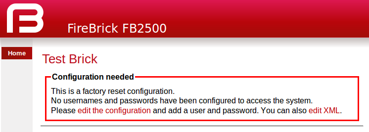
Click on the "edit the configuration" link (red text), or the Wizard menu item, which will take you to the set-up wizard for a new configuration.
The setup wizard allows you to fill in a few key items before entering the normal configuration editor.
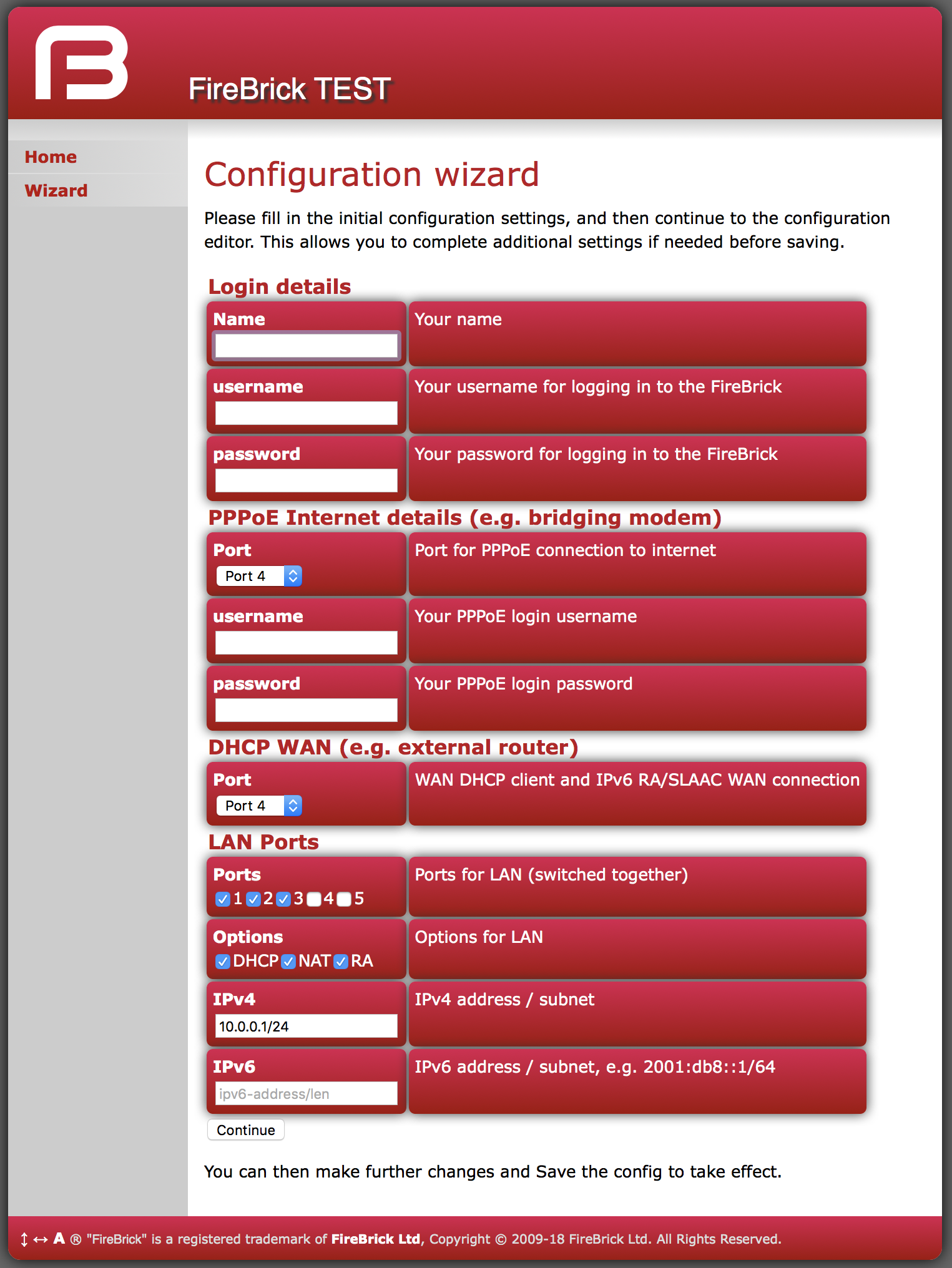
The key settings may vary in later versions, but they represent the main settings you need to consider to get started.
The first part of the wizard covers your login to the FireBrick management interface. There are various ways this access is controlled and locked down, but ultimately this is the way you control your configuration and so they are very important.
For simple security reasons it is better to pick a sensible username, and not admin
For good security reasons you should create a long, easy to remember, but hard to guess, password. There is no limit on how long you make the password, so you can create a complete pass phrase (i.e. a sentence) if you prefer. Remember that upper/lower case matter as do spaces. The FireBrick does not make any attempt to enfoce password policy and will allow you to use a stupid password if you wish, just not a blank one.
Once you have finished the process for your initial config, and logged in, we strongly recommend setting up a two factor authentication using a one time password app on a mobile phone, etc.
There are two main ways the FB2700 is connected to the Internet - either using a PPPoE device such as a bridging modem or an external router that provides access via DHCP setting of a WAN address.
The wizard allows you to set these up, either or both, with PPPoE login/password on a port, and DHCP client on a port, as a WAN interface.
Note
If you use the wizard to make a WAN Ethernet port, you will no longer be able to access the web control pages via that interface as it will not be considered local.The factory default configuration provides a WAN and LAN. In the case of the LAN, several separate ports are configured as independant LAN subnets. The wizard allows you to define a LAN with one or more ports as a switched port group and define an IPv4 and IPv6 subnet that is used on that LAN. You can set a number of options for DHCP, SLAAC, etc.
Note
Typically an ISP connection via PPPoE will Prefix Delegate IPv6 address blocks so these do not usually need to be set up manually.Having completed the initial wizard questions you will then find yourself in the normal configuration editor. You can make any more changes you need to the initial configuration, and then save this.
Once saved you are prompted to login using the username/password details you provided.
Note
The wizard makes no attempt to check the details you entered, these simply become part of that initial configuration. As such you may see error messages when you try to save the config, and will need to make corrections before you can proceed.Note
If you have changed the LAN IP address settings and are using DHCP on your connected computer you may find you need to get a new address and re-connect to the FireBrick control pages at this point.Table of Contents
The FB2700 has, at its core, a configuration based on a hierarchy of objects, with each object having one or more attributes. An object has a type, which determines its role in the operation of the FB2700. The values of the attributes determine how that object affects operation. Attributes also have a type (or datatype), which defines the type of data that attribute specifies. This in turn defines what the valid syntax is for a value of that datatype - for example some are numeric, some are free-form strings, others are strings with a specific format, such as a dotted-quad IP address. Some examples of attribute values are :-
- IP addresses, and subnet definitions in CIDR format e.g. 192.168.10.0/24
- free-form descriptive text strings, e.g. a name for a firewall rule
- Layer 4 protocol port numbers e.g. TCP ports
- data rates used to control traffic shaping
- enumerated values used to control a feature e.g. defining Ethernet port LED functions
The object hierarchy can be likened to a family-tree, with relationships between objects referred to using terms such as Parent, Child, Sibling, Ancestor and Descendant. This tree-like structure is used to :-
- group a set of related objects, such as a set of firewall rules - the parent object acts as a container for a group of (child) objects, and may also contribute to defining the detailed behaviour of the group
- define a context for an object - for example, an object used to define a locally-attached subnet is a child of an object that defines an interface, and as such defines that the subnet is accessible on that specific interface. Since multiple interfaces can exist, other interface objects establish different contexts for subnet objects.
Additional inter-object associations are established via attribute values that reference other objects, typically by name, e.g. a firewall rule can specify one of several destinations for log information to be sent when the rule is processed.
The term 'object model' is used here to collectively refer to :-
- the constraints that define a valid object hiearchy - i.e. which object(s) are valid child objects for a given parent object, how many siblings of the same type can exist etc.
- for each object type, the allowable set of attributes, whether the attributes are mandatory or optional, their datatypes, and permissible values of those attributes
The bulk of this User Manual therefore serves to document the object model and how it controls operation of the FB2700.
Tip
This version of the User Manual may not yet be complete in its coverage of the full object model. Some more obscure attributes may not be covered at all - some of these may be attributes that are not used under any normal circumstances, and used only under guidance by support personnel. If you encounter attribute(s) that are not documented in this manual, please refer in the first instance to the documentation described in Section 3.2.1 below. If that information doesn't help you, and you think the attribute(s) may be relevant to implementing your requirements, please consult the usual support channel(s) for advice.
The object model has a formal definition in the form of an XML Schema Document (XSD) file, which is itself an XML file, normally intended for machine-processing. A more readable version of this information is available in Appendix M.
Note, however, that this is reference material, containing only brief descriptions, and intended for users who are familiar with the product, and in particular, for users configuring their units primarily via XML.
The XSD file is also available on the software downloads website by following the "XSD" link that is present against each software release.
Most objects have a comment attribute which is free-form text that can be used for any purpose. Similarly, most objects have a
source attribute that is intended for use by automated configuration management tools. Neither of these attributes have a direct
effect on the operation of the FB2700.
Many objects have a name attribute which is mandatory and often needs to be unique within the list of objects.
This allows the named object to be referenced from other attributes.
The data type for these is typically an NMTOKEN which is a variant of a string type that does not
allow spaces. If you include spaces then they are removed automatically. This helps avoid any problems referencing names in other places
especially where the reference may be a space separated list.
Many objects have a graph attribute. This allows a graph name to be specified. However, the actual graph name will be
normalised to avoid spaces and limit the number of characters. Try to keep graph names as basic characters (letters, numbers)
to avoid confusion.
The configuration objects are created and manipulated by the user via one of two configuration methods :
- web-based graphical User Interface accessed using a standard web-browser (uses javascript).
- an XML (eXtensible Markup Language) file representing the entire object hierarchy, editable via the web interface or can be uploaded to the FB2700
The two methods operate on the same underlying object model, and so it is possible to readily move between the two methods - changes made via the User Interface will be visible as changes to the XML, and vice-versa. Which method you use is entirely up to you, and some users prefer one or the other, or may make some changes in one of the other. Some operations, such as changing the order of a list of objects, is easier in the XML editor, for example. The web based editor means you do not have to find/remember the attribute names as they are all presented to you. For more information on using XML, refer to Section 3.7.
Whilst we aim to minimise the need for changes to existing configurations, occasionally a change to the object model will need to be made (usually in the interests of flexibility and clarity) that results in changes to the way options are expressed.
During a software upgrade that requires changes to be made the current config will be automatically transformed so that things keep working as they were before wherever possible.
We need to keep track of transformations that are not idempotent (that is applicable repeatedly without side effects). The patch attribute notes the config version to avoid those transformations being applied repeatedly.
Configs downloaded from the FireBrick will have the patch attribute, so that if they are stored and uploaded to a later version they will be correctly transformed.
However the transformations aren't kept around forever, and are periodically cleared out in breakpoint releases (see Section 4.3.1.1 for more info).
If you wish to upload a config targetted for the current version without transformation simply omit the patch attribute.
The FB{PRODUCT} will warn during the upload of configurations with a patch version higher than that supported bv the software.
All of the actual values in the configuration are provided by means of XML attributes, and so they are represented as a string of characters. The value is escaped as per XML rules, e.g. & for &, < for <, > for > and " for " within the string between the quote marks for the attribute value.
Obviously, even though all data is just a string, there are actually different data types, as defined in Section M.4, some of which have value restrictions (range of numbers, or specific string lengths, etc). Some of these are described in more details here.
When you send the FireBrick a configuration the value is parsed and stored internally in a binary format. This means that when you access the config later it is possible the value you see is a normalised version of the value. For example storing a number as 000123 will return as 123.
In some cases you can enter a value in a format you will never see come back when you view the config. For example, simple integers can have SI magnitide suffixes, e.g. G (giga), M (mega), or k (kilo), so you can enter 1.5k but will see 1500. You can also use Gi (gibi), Mi (mebi), or Ki (kibi) for IEC units based on powers of two. You can also suffix B to mean bytes and the resulting value stored will be 8 times larger (as integers are used for bits/second speed settings). Other examples include using colour names like red which you see as #ff0000.
Where the type is in fact a list of a type, the actual value in the XML attribute is actually a space separated list. This is consistent with the XSD (XML Schema Definition). In the web based editor such lists are automatically split on to separate lines to make it easier to read and edit, but in the raw XML the list simple uses a single space between each item.
For example allow="192.168.0.0/16 10.0.0.0/8 172.16.0.0/12" lists three IP prefixes to allow.
Some types are simply a set of acceptable values, the simplest of which is Boolean allowing false and true.
The simple lists of values are detailed in Section M.2, with the acceptable values.
However, in some cases a data type is a reference to some other object, in which case the acceptable values are the name of those referenced objects. In most cases the web based config can ensure it provides a pull down menu of the acceptable values.
There is one special case for IP groups where the value can be an IP address, or range, or the name of an IP group. In this case the web config editor expects you to correctly type the name of an IP group.
There is one other special case of graph names where you can typically enter any name, including one of the defined shaper names or make up a new name as you wish with no error when you save the config. Graphs are created on the fly and so you have to be careful to correctly type graph names in the config to get the desired effect.
As per normal XML Schema rules, dates and times are in ISO8601 format, e.g. 2023-04-28 or 2023-04-28T16:37:48.
However, unlike XML Schema rules, durations are in the format for HH:MM:SS, or MM:SS, or just seconds, e.g. 1:00:00 for one hour. However, to allow XML Schema compliant input a duration can also be entered in the normal format such as PT1H for one hour, which appears as 1:00:00. Note that P1M and PT1M specify 1 month and one minute durations, respectively.
Colours can be entered in normal css style format such as #FF0000 or #F00, or use a small set of colour names such as red. A fourth byte for transparency can be provided if applicable.
There are two cases where the information entered in the config may be sensitive. One case is a password, for example one used for a user log in to the FireBrick. This this case you can provide a simple text password in the config you send, but what you get back will be a hash, e.g. SHA256#92E12F9A333C68690078AC041CD840996EB366A190F7D8966C48AB84A5729F66DCBC7C1A019FC277583684E81015EA. The exact format used may change over time, and if an older hash, such as MD5 exists in the config, it will actually change to a newer hash format automatically next time someone logs in using that password. The hashes include salt to make them harder to crack, but none the less it is best to keep config files secure and not reveal the hashes used.
Another special case is the use of a OTP (One Time Passcode) system. You can put a plain text password and a BASE32 OTP seed in the config for a user, and they will come back as a hashed password (as above), and a # followed by base64 coded data for the OTP code.
In addition, there are also secrets which are passwords which cannot be stored in a hashed format (because of the way they are used). Both passwords and secrets are only displayed if you have full access to the config. If you have limited access, or select to view the config with secrets hidden then they all appear as "secret". However such secrets are stored in the config file in plain text.
It is possible (though complex) for you to make hashes and OTP seeds off-line and simply store in the config. For more information on how passwords are hashed and OTP seeds are stored, see Appendix L.
Being an IP based firewall / router the FireBrick config has a lot of places where an IP address can be entered. In some cases a simple single IP address, but in other cases as an IP and subnet size (CIDR notation) or even a range of IP addresses. Often a list of IP addresses and/or ranges can be specified in a space separated list.
Where a simple IP address is expected you can enter in any valid format for IP addresses. In some cases the field may specifically be IPv4 or IPv6 but in most cases either type of IP address can be entered. In the case of IPv6, the :: shortened format is accepted, and used on output. The legacy format, e.g. 2001:db8::192.168.0.1 format is also accepted as per IPv6 RFCs.
There is also a case where up to one IPv4 and up to one IPv6 address can be specified (separated by a space), e.g. when setting the source IP address for some protocol.
In some cases an IP address and subnet length is expected (in CIDR format), e.g. 192.168.0.1/24. There are two variations of this, one is a subnet which includes an IP address and length, such as 192.168.0.1/24. The other case is where the prefix is what matters, and so the IP address can be any within the prefix, so 192.168.0.1/24 would actually read back as 192.168.0.0/24.
Where the subnet is one IP, e.g. 192.168.0.1/32 it can be provided as, and reads back as a simple IP address, i.e. 192.168.0.1.
In some cases a range of IP addresses is needed, for example when making a filter for firewall rules or allow lists.
For IPv4 addresses this can use a format using a hyphen, e.g. 192.168.0.100-199. Where the range is wider there may be more after the hyphen, e.g. 192.168.0.100-1.99 is all from 192.168.0.100 to 192.168.1.99. Ultimately it can be a complete range such as 10.1.2.3-11.100.2.5, though that is rarely needed.
Where a range covers all parts after the hyphen then an X can be used, e.g. 10.2-4.X.X for 10.2.0.0 to 10.4.255.255.
A range can be provided as a simple IP address (for one IP in range) or as a CIDR format. IPv6 address ranges can only be CIDR format prefixes. If a range happens to be a CIDR range it shows in that format. E.g. 192.168.0.0-192.168.255.255 will read back as 192.168.0.0/16.
In some cases a list of IP ranges can also include named IP groups. In which case the IP groups are checked by name, firstly in the case of a rule-set where ip-group entries are specified, then system ip-group entries, and then named subnet entries (including DHCP client subnets).
In somes cases a filter needs to be specified to allow a set of prefixes to be defined, such as BGP filters.
In this case the format has a range of prefix lengths using a hyphen, e.g. 10.0.0.0/8-24. The prefix must match at least the lower size bits (/8 in that example), but can be any size in the range.
Where the format uses either end of the range it can be omitted either side of the hyphen, e.g. 10.0.0.0/8- is the same as 10.0.0.0/8-32.
Some cases need to be more complex and a colon is used to add a third bit length, e.g. 10.0.0.0/8:16-24 means all prefixes within 10.0.0.0/8 which are a prefix length of 16 to 24 bits, so that would include 10.1.0.0/17 in that case.
This section provides an overview of how to use the web-based User Interface. We recommend that you read this section if you are unfamiliar with the FB2700, so that you feel comfortable with the design of the User Interface. Later chapters cover specific functionality topics, describing which objects are relevant, any underlying operational principles that are useful to understand, and what effect the attributes (and their values) have.
The web-based User Interface provides a method to create the objects that control operation of the FB2700. Internally, the User Interface uses a formal definition of the object model to determine where (in the hierarchy) objects may be created, and what attributes may exist on each object, so you can expect the User Interface to always generate valid XML. [1]
Additionally, the web User Interface provides access to the following items :-
- status information, such as DHCP server allocations, FB105 tunnel information and system logs
- network diagnostic tools, such as Ping and Traceroute ; there are also tools to test how the FB2700 will process particular traffic, allowing you to verify your firewalling is as intended
- traffic graphs
By default, access to the web user interface is available to all users, from any locally connected IP address. If you don't require such open access, you may wish to restrict access using the settings described in Section 15.3.
The User Interface has the following general layout :-
- a 'banner' area at the top of the page, containing the FireBrick logo, model number and system name
- a main-menu, with sub-menus that access various parts of the user interface; the main-menu is normally displayed on the left side, although on smaller displays (e.g. smartphones) it may be accessed via the 3 horizontal lines in the top right corner.
- a 'footer' area at the bottom of the page, showing the current software version
- the remaining page area contains the content for the selected part of the user-interface
Note that the main-menu items themselves have a specific function when clicked - clicking such items displays a general page related to that item - for example, clicking on Status shows some overall status information, whereas sub-menu items under Status display specific categories of status information.
The user interface pages used to change the device configuration are referred to as the 'config pages' in this manual - these pages are accessed by clicking on the "Edit" item in the sub-menu under the "Config" main-menu item.
Note
The config pages utilise JavaScript for their main functionality ; you must therefore have JavaScript enabled in your web browser in order to configure your FB2700 using the web interface.
The structure of the config pages mirrors the object hierarchy, and therefore they are themselves naturally hierachical. Your position in the hierarchy is illustrated in the 'breadcrumbs' trail at the top of the page, for example :-
Firewall/mapping rules :: rule-set 1 of 3 (filters) :: rule 7 of 19 (ICMP)
This shows that the current page is showing a rule, which exists within a rule-set, which in turn is in the "Firewall/mapping rules" category (see below).
Configuration objects are grouped into a number of categories. At the top of the config pages is a set of icons, one for each category, as shown in Figure 3.1 :-
Within each category, there are one or more sections delimited by horizontal lines. Each of these sections has a heading, and corresponds to a
particular type of top-level object, and relates to a major part of the configuration that comes under the
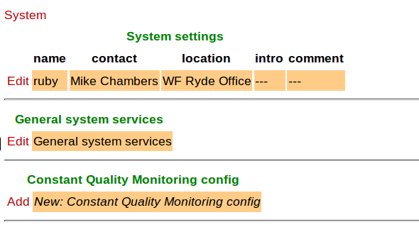
selected category. See Figure 3.2 for an example showing part of the "Setup" category, which
includes general system settings (the system object) and control of system services (network services provided by the FB2700, such as the web-interface
web server, telnet server etc., controlled by the services object).
Each section is displayed as a tabulated list showing any existing objects of the associated type. Each row of the table corresponds with one object, and a subset (typically those of most interest at a glance) of the object's attributes are shown in the columns - the column heading shows the attribute name. If no objects of that type exist, there will be a single row with an "Add" link. Where the order of the objects matter, there will be an 'Add' link against each object - clicking an 'Add' link for a particular object will insert a new object before it. To add a new object after the last existing one, click on the 'Add' link on the bottom (or only) row of the table.
Tip
If there is no 'Add' link present, then this means there can only exist a limited number of objects of that type (possibly only one), and this many already exist. The existing object(s) may have originated from the factory reset configuration.
You can 'push-down' into the hierarchy by clicking the 'Edit' link in a table row. This takes you to a page to edit that specific object. The page also shows any child objects of the object being edited, using the same horizontal-line delimited section style used in the top-level categories. You can navigate back up the hierarchy using various methods - see Section 3.6.3.
Caution
Clicking the "Add" link will create a new sub-object which will have blank/default settings. This can be useful to see what attributes an object can take, but if you do not want this blank object to be part of the configuration you later save you will need to click Erase. Simply going back "Up" or moving to another part of the config will leave this newly created empty object and that could have undesirable effects on the operation of your FireBrick if saved.The details of an object are displayed as a matrix of boxes (giving the appearance of a wall of bricks),
one for each attribute associated with that object type. Figure 3.3
shows an example for an interface object (covered in Chapter 6) :-
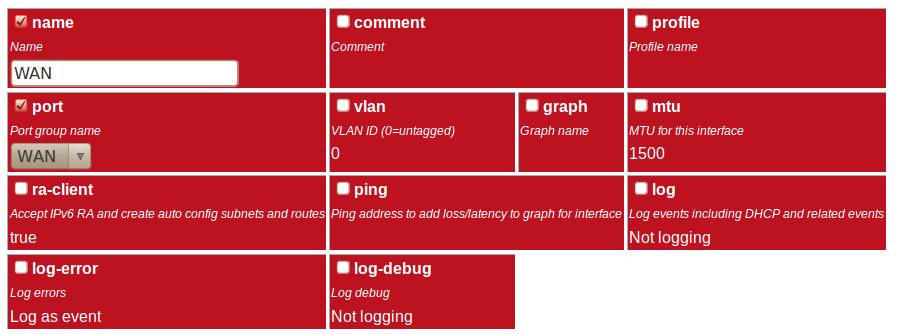
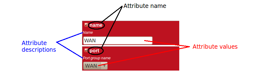
By default, more advanced or less frequently used attributes are hidden - if this applies to the object being edited, you will see the text shown in Figure 3.4. The hidden attributes can be displayed by clicking on the link "Show all".

Each brick in the wall contains the following :-
- a checkbox - if the checkbox is checked, an appropriate value entry widget is displayed, otherwise, a default value is shown and applied for that setting. If the attribute is not optional then no checkbox is show.
- the attribute name - this is a compact string that exactly matches the underlying XML attribute name
- a short description of the attribute
Tip
If there is no default shown for an attribute then its value, if needed, is zero, blank, null, empty string, false (internally it is zero bits!). In some cases the presence of an attribute will have meaning even if that attribute is an empty string or zero value. In some cases the default for an attribute will not be a fixed value but will depend on other factors, e.g. it may be "auto", or "set if using xyz...". The description of the default value should make this clear. Where an optional attribute is not ticked the attribute does not appear in the XML at all.These can be seen in Figure 3.5 :-
If the attribute value is shown in a 'strike-through' font (with a horizontal line through it mid-way vertically), this illustrates that the attribute can't be set - this will happen where the attribute value would reference an instance of particular type of object, but there are not currently any instances of objects of that type defined.
Tip
Since the attribute name is a compact, concise and un-ambiguous way of referring to an attribute, please quote attribute names when requesting technical support, and expect technical support staff to discuss your configuration primarily in terms of attribute (and object/element) names, rather than descriptive text, or physical location on your screen (both of which can vary between software releases).
You navigate around the hierarchy using one or more of the following :-
- configuration category icons
- the breadcrumbs - each part of the breadcrumbs (delimited by the :: symbol) is a clickable link
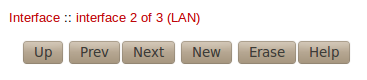
- the in-page navigation buttons, shown in Figure 3.6 : "Up" - move one level up in the object hierarchy, "Prev" - Previous object in a list, and "Next" - Next object in a list.
Caution
The configuration pages are generated on-the-fly using JavaScript within your web browser environment (i.e. client-side scripting). As such, the browser is essentially unaware of changes to page content, and cannot track these changes - this means the browser's navigation buttons (Back, Forward), will not correctly navigate through a series of configuration pages.
Please take care not to use the browser's Back button whilst working through configuration pages - navigation between such pages must be done via the buttons provided on the page - "Prev", "Next" and "Up".
Navigating away from an object using the supported navigation controls doesn't cause any modifications to that object to be lost, even if the configuration has not yet been saved back to the FB2700. All changes are initially held in-memory (in the web browser itself), and are committed back to the FireBrick only when you press the Save button.
The navigation button area, shown in Figure 3.6, also includes three other buttons :-
- New : creates a new instance of the object type being edited - the new object is inserted after the current one ; this is equivalent to using the "Add" link one level up in the hierarchy
- Erase : deletes the object being edited - note that the object will not actually be erased until the configuration is saved
- Help : browses to the online reference material (as desribed in Section 3.2.1) for the object type being edited
Caution
If you Add a new object, but don't fill in any parameter values, the object will remain in existence should you navigate away. You should be careful that you don't inadvertently add incompletely set up objects this way, as they may affect operation of the FireBrick, possibly with a detrimental effect.
If you have added an object, perhaps for the purposes of looking at what attributes can be set on it, remember to delete the object before you navigate away -- the "Erase" button (see Figure 3.6) is used to delete the object you are viewing.
To back up / save or restore the configuration, start by clicking on the "Config" main-menu item. This will show a page with a form to upload a configuration file (in XML) to the FB2700 - also on the page is a link "Download/save config" that will download the current configuration in XML format.
It is also possible to set auto-backup-url to a URL (starting https://) to automatically post a copy of the
config to a server of your choice shortly after any changes. There is a delay of a few minutes after the last change before posting the config.
The config post also includes a header X-Signed with a digital signature of the config itself using the private
key stored in the FireBrick Certificates store against the FireBrick serial number. This should be used to check for authenticity of the posted
config.
It is possible to change the colour of the interface's header and footer banners from the config editor. Select the "Setup" category icon and choose to edit "General system services" and then "Web server settings". Click "Show all" at the bottom of the page, and then select "banner-background". By default, this will also change the colour of the config editor and the highlight text colour (used for hyperlinks and headings). If needed, you can also set those colours separately.
Note
Once you have saved (or test saved) the configuration, you will need to navigate to a different page or reload to see the new colours.
Alternatively you can edit the XML configuration file (see Section 3.7)
and set the banner-background attribute for the http
service.
It is also possible to configure an external CSS to use with the FireBrick web
control pages, via the css-url attribute. This allows a great deal of
control of the overall layout and appearance. This can be useful for dealers or IT
support companies to set up FireBricks in a style and branding of their choice.
An XML file is a text file (i.e. contains human-readable characters only) with formally defined structure and content. An XML file starts with the line :-
<?xml version="1.0" encoding="UTF-8"?>
This defines the version of XML that the file complies with and the character encoding in use. The UTF-8 character coding is used everywhere by the FireBrick.
The XML file contains one or more elements, which may be nested into a hiearchy.
Note
In XML, the configuration objects are represented by elements, so the terms object and element are used interchangeably in this manual.
Each element consists of some optional content, bounded by two tags - a start tag AND an end tag.
A start tag consists of the following sequence of characters:-
- a < character
- the element name
- optionally, a number of attributes
- a > character
An end tag consists of the following sequence of characters:-
- a < character
- a / character
- the element name
- a > character
If an element needs no content, it can be represented with a more compact self closing tag. A self closing tag is the same as a start tag but ends with /> and then has no content or end tag.
Since the <, > and " characters have special meaning, there
are special ('escape') character sequences starting with the ampersand character that are used to represent these characters. They are :-
Note that since the ampersand character has special meaning, it too has an escape character sequence.
Attributes are written in the form : name="value" or name='value'. Multiple attributes are
separated by white-space (spaces and line breaks).
Generally, the content of an element can be other child elements or text. However, the FB2700 doesn't use text content in elements - all configuration data is specified via attributes. Therefore you will see that elements only contain one or more child elements, or no content at all. Whilst there is generally not any text between the tags, white space is normally used to make the layout clear.
At the top level, an XML file normally only has one element (the root element), which contains the entire element hierarchy.
In the FB2700 the root element is <config>, and it contains 'top-level' configuration elements that cover major areas
of the configuration, such as overall system settings, interface definitions, firewall rule sets etc.
In addition to this User Manual, there is reference material is available that documents the XML elements - refer to Section 3.2.1.
The XML representation of the configuration can be viewed and edited (in text form) via the web interface by clicking on "XML View" and "XML Edit" respectively under the main-menu "Config" item. Viewing the configuration is, as you might expect, 'read-only', and so is 'safe' in as much as you can't accidentally change the configuration.
An example of a simple, but complete XML configuration is shown below, with annotations pointing out the main elements
<?xml version="1.0" encoding="UTF-8"?> <config xmlns="http://firebrick.ltd.uk/xml/fb9000/"xmlns:xsi="http://www.w3.org/2001/XMLSchema-instance" xsi:schemaLocation="http://firebrick.ltd.uk/xml/fb9000/ ... timestamp="2023-03-14T12:24:07Z" patch="8882"> <system name="gateway"
contact="Peter Smith" location="The Basement" log-support="fb-support"> </system> <user name="peter"
full-name="Peter Smith" password="FB105#4D42454D26F8BF5480F07DFA1E41AE47410154F6" timeout="PT3H20M" config="full" level="DEBUG"/> <log name="default"/>
<log name="fb-support"> <email to="crashlog@firebrick.ltd.uk" comment="Crash logs emailed to FireBrick Support"/> </log> <services>
<time/> <telnet log="default"/> <http/> <dns domain="watchfront.co.uk" resolvers="81.187.42.42 81.187.96.96"/> </services> <port name="WAN"
ports="1"/> <port name="LAN" ports="2"/> <interface name="WAN" port="WAN"> <subnet name="ADSL" ip="81.187.106.73/30"/> </interface> <interface name="LAN"
port="LAN"> <subnet name="LAN" ip="81.187.96.94/28"/> <dhcp name="LAN" ip="81.187.96.88-92" log="default"/> </interface> <rule-set name="filters"
no-match-action="drop"> <rule name="Our-Traffic" source-interface="self" comment="FB originated traffic allowed"/> <rule name="FireBrick UI" target-port="80" target-interface="self" protocol="6"/> <rule name="ICMP" protocol="1" log="default"/> <rule name="All outgoing" source-interface="LAN"/> <rule name="FB-access" source-interface="LAN" target-port="80" target-interface="self" protocol="6" comment="FB web config access"/> <rule name="final-no-match" log="default" action="drop" comment="Catch all - sets default logging for no match"/> </rule-set> </config>
Top level attributes are effectively read only as they are overwritten when a config is uploaded. These are for your information, and include things like the date/time the config was uploaded, and the username and IP address that uploaded the config, etc. | |
sets some general system parameters (see Section 4.2) | |
defines a single user with the highest level of access (DEBUG) (see Section 4.1) | |
defines a log target (see Chapter 5) | |
configures key system services (see Chapter 15) | |
defines physical-port group (see Section 6.1) | |
defines an interface, with one subnet and a DHCP allocation pool (see Chapter 6) | |
defines a set of firewalling rules (see Chapter 7) |
The XML file may be retrieved from the FireBrick, or uploaded to the FireBrick using HTTP transfers done via tools such as curl.
Using these methods, configuration of the FB2700 can be integrated with existing administrative systems.
Note
Linebreaks are shown in the examples below for clarity only - they must not be entered on the command-line
To download the configuration from the FB2700 you need to perform an HTTP GET of the following URL :-
http://<FB2700 IP address or DNS name>/config/config
An example of doing this using curl, run on a Linux box is shown below :-
curl http://<FB2700 IP address or DNS name>/config/config
   --user "username:password" --output "filename"
Replace username and password with appropriate credentials.
The XML configuration file will be stored in the file specified by filename - you can choose any file extension
you wish (or none at all), but we suggest that you use .xml for consistency with the file extension used when
saving a configuration via the User Interface (see Section 3.6.4).
Note
When fetching the config in this way, the initial config attributes will include formal namespace and xsi:schemaLocation attributes. These are not normally shown on the config editor via the web interface, and are ignored when uploading a config.To upload the configuration to the FB2700 you need to send the configuration XML file as if posted by a web form,
using encoding MIME type multipart/form-data.
An example of doing this using curl, run on a Linux box is shown below :-
curl http://<FB2700 IP address or DNS name>/config/config
   --user "username:password" --form config="@filename"
Note
You can also include --form override=true to force the config to be loaded even if it has minor (recoverable) errors, e.g. if it is config for older version of FireBrick.
[1] If the User Interface does not generate valid XML - i.e. when saving changes to the configuration the FireBrick reports XML errors, then this may be a bug - please check this via the appropriate support channel(s).
Table of Contents
You will have created your first user as part of the initial setup of your FB2700, as detailed in either the QuickStart Guide or in Chapter 2 in this manual.
To create, edit or delete users, browse to the config pages by clicking the "Edit" item in the sub-menu under the "Config" main-menu item, then click on the "Users" category icon. Click on the "Edit" link adjacent to the user you wish to edit, or click on the "Add" link to add a user.
To delete a user, click the appropriate "Edit" link, then click the "Erase" button in the navigation controls - see Figure 3.6. As with any such object erase operation, the object will not actually be erased until the configuration is saved.
Once you have added a new user, or are editing an existing user, the object editing page will appear, as shown in Figure 4.1 :-
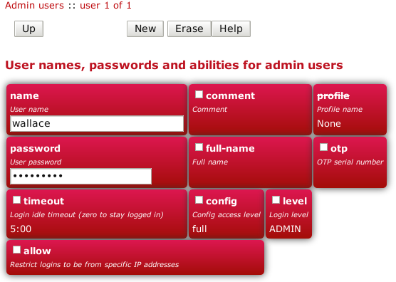
The minimum attributes that must be specified are name, which is the username that you type in when logging in, and
password - passwords are mandatory on the FB2700.
You can optionally provide a full name for the specified username, and a general comment field value.
A user's login level is set with the level attribute, and determines what CLI commands the user can run.
The default, if the level attribute is not specified, is ADMIN - you may wish to downgrade the level for
users who are not classed as 'system administrators'.
Table 4.1. User login levels
| Level | Description |
NOBODY | No access to any menu items, but can access control switches for which the user has access. |
GUEST | Guest user, access to some menu items |
USER | Normal unprivileged user |
ADMIN | System administrator |
DEBUG | System debugging user |
Tip
In general you only want to use NOBODY, ADMIN or DEBUG levels.The configuration access level determines whether a user has read-only or read-write access to the configuration,
as shown in Table 4.2 below. This mechanism can also be used to deny all access to the configuration using the
none level, but still allowing access to other menus and diagnostics.
Config access also requires at least admin level for their login level to access config via the web interface.
It is possible to test a new config, causing it to be applied but not saved to permament storage. This test config automatically reverts after a few minutes if not committed, or if the brick restarts, e.g. power cycle. It is recommended that you test a config first to ensure you have not locked yourself out, and there is a user level to force you to have to test configs first.
Table 4.2. Configuration access levels
| Level | Description |
none | No access unless explicitly listed |
view | View only access (no passwords or hashes) |
read | Read only access (with passwords and hashes) |
demo | Full view and edit access, but can only test new config, not save them. |
test | Full view and edit access, but must test new config before committing it. |
full | Full view and edit access. |
To improve security, login sessions to either the web user interface, or to the command-line interface (via telnet, see Chapter 21),
will time-out after a period of inactivity. This idle time-out defaults to 5 minutes, and can be changed by setting the timeout attribute
value.
The time-out value is specified using the syntax for the XML fb:duration data type. The syntax is hours, minutes and seconds, or minutes and seconds or just seconds. E.g. 5:00.
To set a user's time-out in the user interface, tick the checkbox next to
timeout, and enter a value in the format described above.
Setting a timeout to 0 means unlimited and should obviously be used with care.
You can restrict logins by a given user to be allowed only from specific IP addresses, using the allow attribute.
This restriction is per-user, and is distinct from, and applies in addition to, any restrictions specified on either the web or telnet (for command
line interface access) services (see Section 15.3 and Section 15.4), or any firewall rules that affect web or
telnet access to the FB2700 itself.
The FireBrick allows a general definition of IP groups which allow a name to be used in place of a range of IP addresses. This is a very general mechanism that can be used for single IP addresses or groups of ranges IPs, e.g. admin-machines may be a list or range of the IP addresses from which you want to allow some access. The feature can also be useful even where only one IP is in the group just to give the IP a meaningful name in an access list.
These named IP groups can be used in the allow list for a user login, along with specific IP addresses or ranges if needed.
However, IP groups can also list one or more user names and implicitely include the current IP address from which those users are logged in to the web interface. This can be useful for firewall rules where you may have to log in to the FireBrick, even as a NOBODY level user, just to get your IP address in an access list to allow further access to a network from that IP.
By specifying a profile name using the profile attribute, you can allow logins by the user only when the
profile is in the Active state (see Chapter 9). You can use this to, for example, restrict logins to be allowed only during
certain times of the day, or you can effectively suspend a user account by specifying an always-Inactive profile.
Normally, all config data is updated via the config edit process, and this allows a new password to be set for any user.
However, there is also a menu to allow a logged in user to change their own password. This does not require the user to have any config access permission. Simply enter the old password, and the new password twice and the password is updated.
If you have set up an OTP configuration for a user, then you cannot change the password simply using the configuration editor (unless also setting a new OTP configuration from scratch or removing it). In such cases the password should be set using the password change web page. This is also good practice as it avoids the administrator knowing people's passwords.
A login to the FireBrick normally requires only a username and password. However you can configure an additional security measure using a One Time Password (OTP) device. These are available as key fobs that show a code, but are more commonly done by use of a mobile phone application.
In order for the device to work you need a key which is known to the FireBrick and the device. However, this is very simple to set up. A user can access the Password / OTP menu where a random key is allocated and displayed within a QR 2D bar code. Most authenticator applications simply scan the QR code and start showing the 6 digit number on the display (which changes every 30 seconds). You then enter your password and a code from your device to complete the process.
It is possible for anyone with configuration access to edit your user settings and remove the OTP settings if you wish. This can be useful if you lose or break the phone, for example. You may want to keep a local configuration user as a backup as well, as OTP cannot be used if the clock is not set for any reason.
When you login, after you submit your username and password you are asked for a code from the authenticator to complete the login process.
It is also possible to enter the password as the authenticator code followed by the configured password. This is useful if using HTTP authentication to access a web page where there is no separate option for the authenticator input to be provided.
If OTP is configured you can leave the password blank (which is not normally allowed) and hence use the authenticator code as the entire password, though this is not recommended for security reasons as it also means the TOTP seed is recoverable from the config.
Note
Technical details to allow you to create configs with password and OTP seed hashes are described in Appendix L.The system top-level object can specify attributes that control general, global system settings. The available attributes are
described in the following sections, and can be configured in the User Interface by choosing the "Setup" category, then
clicking the "Edit" link under the heading "System settings".
The software auto upgrade process is controlled by system objects attributes - these are described in Section 4.3.3.2.
The system name, also called the hostname, is used in various aspects of the FB2700's functions, and so we recommend you set the hostname to something appropriate for your network.
The hostname is set using the name attribute.
The attributes shown in Table 4.3 allow you to specify general administrative details about the unit :-
Table 4.3. General administrative details attributes
| Attribute | Purpose |
comment | General comment field |
contact | Contact name |
intro | Text that appears on the 'home' page - the home page is the first page you see after logging in to the FB2700. This text is also displayed immediately after you log in to a command-line session. |
location | Physical location description |
The log and log-... attributes control logging of events related to the operation of the system itself.
For details on event logging, please refer to Chapter 5, and for details on the logging control attributes on system
object, please refer to Section 5.7.
The home page is the first page you see after logging in to the FB2700, or when you click the Home main-menu item. The home page displays
the system name, and, if defined, the text specified by the intro attribute on the system object.
Additionally, you can define one or more web links to appear on the home page. These are defined using link objects, which
are child objects of the system object.
To make a usable link, you must specify the following two attributes on the link object :-
text: the text displayed as a hyperlinkurl: link destination URL
Additionally, you can name a link, specify a comment, and make the presence of the link on the home page conditional on a profile.
FB2700 users benefit from FireBrick's pro-active software development process, which delivers fast fixes of important bugs, and implementation of many customer enhancement requests and suggestions for improvement. As a matter of policy, FireBrick software upgrades are always free to download for all FireBrick customers.
To complement the responsive UK-based development process, the FB2700 is capable of downloading and installing new software directly from Firebrick's servers, providing the unit has Internet access.
This Internet-based upgrade process can be initiated manually (refer to Section 4.3.3.1), or the FB2700 can download and install new software automatically, without user intervention.
If the unit you want to upgrade does not have Internet access, then new software can be uploaded to the unit via a web browser instead - see Section 4.3.4.
Caution
Software upgrades are best done using the Internet-based upgrade process if possible - this ensures the changes introduced by Breakpoint releases are automatically accounted for (see Section 4.3.1.1)
Software upgrades will trigger an automatic reboot of your FB2700 - this will cause an outage in routing, and can cause connections that are using NAT to drop. However, the FB2700 reboots very quickly, and in many cases, users will be generally unaware of the event. You can also use a profile to restrict when software upgrades may occur - for example, you could ensure they are always done overnight. The reboot will close all L2TP connections first. The reboot will close all BGP sessions first. The reboot will wait for all VoIP calls to complete before rebooting.
There are three types of software release : factory, beta and alpha. For full details on the differences between these software releases, refer to the FB2700 software downloads website - please follow the 'read the instructions' link that you will find just above the list of software versions.
Note
In order to be able to run alpha releases, your FB2700 must be enabled to run alpha software - this is done by changing the entry in the FireBrick capabilities database (hosted on FireBrick company servers) for your specific FB2700, as identified by the unit's Serial Number. Normally your FB2700 will be running factory or possibly beta software, with alpha software only used under advice and guidance of support personnel while investigating/fixing possible bugs or performance issues. You can see whether your FB2700 is able to run alpha releases by viewing the main Status page (click the Status main menu-item), and look for the row labelled "Allowed" - if the text shows "Alpha builds (for testing)" then your FB2700 can run alpha releases.
Sometimes the configuration will need to be transformed during an upgrade, these transformations will be automatically performed when needed as part of the upgrade (see Section 3.4 for details). However we do not keep the update procedures around forever, instead we flag certain releases as breakpoints that upgrades must go through sequentially to maintain a valid configuration.
Note
Between breakpoints changes to config could be made, for instance in alpha releases. These transformations will be kept around until at least the next breakpoint release to maintain compatibility.
When using the Internet-based upgrade process, the FB2700 will always upgrade to the next available breakpoint version first, so that the configuration is updated appropriately. If your current software version is several breakpoint releases behind the latest version, the upgrade process will be repeated for each breakpoint release, and then to the latest version if that is later than the latest breakpoint release.
On the FB2700 software downloads website, breakpoint releases are labelled [Breakpoint] immediately under the version
number.
Note
If you have saved copies of configurations for back-up purposes, we recommend saving a new version after upgrading to a breakpoint release.
If you use automated methods to configure your FB2700, you will need to check the documentation to see whether those methods need updating before the next breakpoint release.
Downgrading the software past a release that makes configuration changes will (provided the running version is recent enough to have this feature) show a warning that the current configuration patch version is too recent.
In this case check that the configuration looks correct for the running version, and correct or remove the patch attribute (this can be done in the XML editor, or by making any change in the UI based editor).
The current software version is displayed on the main Status page, shown when you click the Status main menu-item itself (i.e. not a submenu item). The main software application version is shown next to the word "Software", e.g. :-
Software FB9001 TEST Abbotscliffe (V2.00.100 2023-10-09T14:52:22)
The software version is also displayed in the right hand side of the 'footer' area of each web page, and is shown immediately after you log in to a command-line session.
Note
'Out of the box' the FB2700 is configured to automatically download and install new factory releases. This is a safe option, and we expect many users to be happy with this - however, if you would prefer, this process can be disabled - refer to Section 4.3.3.2.
If automatic installs are allowed, the FB2700 will check for new software on boot up and approximately every 24 hours thereafter - your FB2700 should therefore pick up new software at most ~ 24 hours after it is released. You can choose to allow this process to install only new factory-releases, factory or beta releases, or any release, which then includes alpha releases (if your FB2700 is enabled for alpha software - see Section 4.3.1) - refer to Section 4.3.3.2 for details on how to configure auto upgrades.
Caution
Alpha releases may be unstable, and so we do not generally recommend setting your FB2700 to automatically install alpha releases.Whenever you browse to the main Status page, the FB2700 checks whether there is newer software available, given the current software version in use, and whether alpha releases are allowed. If new software is available, you will be informed of this as shown in Figure 4.2 :-
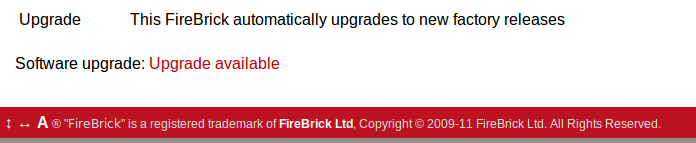
To see what new software is available, click on the "Upgrade available" link. This will take you to a page that will show Release notes that are applicable given your current software version, and the latest version available. On that page there is an "Upgrade" button which will begin the software upgrade process.
There are two attributes on the system object (see Section 4.2) that affect the automatic software upgrade process :-
Table 4.4. Attributes controlling auto-upgrades
| Attribute | Description |
sw-update | Controls what types of software releases the auto-upgrade process will download/install. This attribute can also be used to
disable the auto-upgrade process - use the value of false to achieve this.
|
sw-update-profile | Specifies the name of a profile to use to control when software upgrades are attempted (see Chapter 9 for details on profiles). |
sw-update-delay | Specifies a minimum number of days after release to attempt the upgrade (intended for automating staggered upgrades). |
The current setting of sw-update (in descriptive form) can be seen on the main Status page, adjacent to the word "Upgrade", as shown in
Figure 4.2 (in that example, sw-update is set to, or is defaulting to, factory).
This method is entirely manual, in the sense that the brick itself does not download new software from the FireBrick servers, and responsibilty for loading breakpoint releases as required lies with the user.
In order to do this, you will first need to download the required software image file (which has the file extension .img) from the
FB2700 software downloads website
onto your PC.
The next step is the same as you would perform when manually-initiating an Internet-based upgrade i.e. you should browse to the main Status page, where, if there is new software is available, you will be informed of this as shown in Figure 4.2.
This step is necessary since the manual upgrade feature currently shares the page used for Internet-based manual upgrades, which is reached by clicking "Upgrade available" link. After clicking this link, you will find the manual upgrade method at the bottom of the page, as shown in Figure 4.3 :-
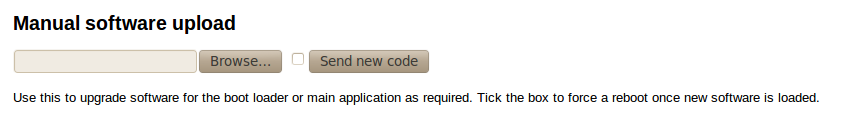
The FB2700 contains internal Flash memory storage that holds two types of software :-
- main application software (generally referred to as the app)
- a bootloader - runs immediately upon power-up, initialises the system, and then loads the app
It is possible for only one of these types of software, or neither of them, to be present in the Flash, but when shipped from the factory the unit
will contain a bootloader and the latest factory-release application software. The FB2700 can store multiple app software images in the Flash,
and this is used with an automatic fall-back mechanism - if a new software image proves unreliable, it is 'demoted', and the unit falls back
to running older software. The show flash contents CLI command can be used to see what is stored in the Flash - see
Appendix J.
The status LED has three defined states, as shown in Table 4.5 below :-
Table 4.5. Status LED indications
| Indication | Status |
| Off | No power applied to unit (or possibly hardware fault) |
| Flashing with approximately 1 second period | Bootloader running / waiting for network connection |
| On | Main application software running |
After power-up, the normal LED indication sequence is therefore to go through the ~1 second period flashing phase, and then - if at least one Ethernet port is connected to an active device , or after a few seconds waiting for a factory reset cable - change to solid once the app is running.
From power-up, an FB2700 will normally boot and be operational in under five seconds.
Whilst the bootloader is waiting for an active Ethernet connection, the green and yellow LEDs by the ports flash in a continual left-to-right then right-to-left sequence. The port LEDs on the panel on the opposite side to the physical ports also flash, in a clockwise sequence.
Note
The same port LED flashing sequences (but this time in red) are observed if the app is running and none of the Ethernet ports are connected to an active link-partner. Note that the app continues to run, and the power/status LED will still be on solid.
When connected to an active link-partner, these flashing sequences will stop and the port LEDs will start indicating physical port status, with various status indications possible, controllable via the configuration (see Section 6.4).
Table of Contents
Many events in the operation of the FireBrick create a log entry. These are a one-line string of text saying what happened. This could be normal events such as someone logging into the web interface, or unusual events such as a wrong password used, or DHCP not being able to find any free addresses to allocate.
A log target is a named destination (initially internal to the FB2700) for log entries - you can set up multiple log targets which you can use to separate out log event messages according to some criteria - for example, you could log all firewalling related log events to a log target specifically for that purpose. This makes it easier to locate events you are looking for, and helps you keep each log target uncluttered with un-related log events - this is particularly important when when you are logging a lot of things very quickly.
A log target is defined using a log top-level object - when using the web User Interface, these objects are in the "Setup" category,
under the heading "Log target controls".
Every log entry is put in a buffer in RAM, which only holds a certain number of log entries (typically around 1MB of text) - once the buffer is full, the oldest entries are lost as new ones arrive. Since the buffer is stored in volatile memory (RAM), buffer contents are lost on reboot or power failure.
This buffer can be viewed via the web interface or command line which can show the history in the buffer and then follow the log in real time (even when viewing via a web browser, with some exceptions - see Section 5.6.1).
In some cases it is essential to ensure logged events can be viewed even after a power failure. You can flag a log target to log to the non-volatile Flash memory within the FB2700, where it will remain stored even after a power failure. You should read Section 5.5 before deciding to log events to Flash memory.
Each log target has various attributes and child objects defining what happens to log entries to this target. However,
in the simplest case, where you do not require non-volatile storage, or external logging (see Section 5.3),
the log object will only need a name attribute, and will have no child objects. In XML this will look something like :-
<log name="my_log"/>
The internal Flash memory logging system is separate from the external logging. It applies if the log target object has flash="true".
It causes each log entry to be written to the internal non-volatile Flash log as it is created.
The flash log is intended for urgent permanent system information only, and is visible using the show flash log CLI command (see
Appendix J for details on using this command). Chapter 21 covers the CLI in general.
Caution
Flash logging slows down the system considerably - only enable Flash logging where absolutely necessary.
The flash log does have a limit on how much it can hold, but it is many thousands of entries so this is rarely an issue. Oldest entries are automatically discarded when there is no space.
The console is the command line environment described in Chapter 21.
You can cause log entries to be displayed as soon as possible on the console (assuming an active console session) by setting
console="true" on the log target.
You can stop the console logging with troff command or restart it with tron command.
Event logging is enabled by setting one of the attributes shown in Table 5.1 on the appropriate
object(s) in the configuration, which depends on what event(s) you are interested in. The attribute value specifies the name of the log target to send
the event message to. The events that cause a log entry will
naturally depend on the object on which you enable logging. Some objects have additional attributes such as log-error for unusual events,
and log-debug for extra detail.
Table 5.1. Logging attributes
| Attribute | Event types |
log | This is normal events. Note that if log-error is not set then this includes errors. |
log-error | This is when things happen that should not. It could be something as simple as bad login on telnet. Note that if log-error is
not set but log is set then errors are logged to the log target by default. |
log-debug | This is extra detail and is normally only used when diagnosing a problem. Debug logging can be a lot of information, for example, in some cases whole packets are logged (e.g. PPP). It is generally best only to use debug logging when needed. |
Entries in the buffer can also be sent on to external destinations, such as via email or syslog. Support for sending a text message via SMS (using a suitable dongle attached to the USB port), triggering SNMP traps and logging to a USB memory stick may be provided in a future software release.
You can set these differently for each log target. There is inevitably a slight lag between the event happening and the log message being sent on, and in some cases, such as email, you can deliberately delay the sending of logs to avoid getting an excessive number of emails.
If an external logging system cannot keep up with the rate logs are generated then log entries can be lost. The fastest type of external logging is using syslog which should manage to keep up in pretty much all cases.
The FB2700 supports sending of log entries across a network to a syslog server. Syslog is described in RFC5424, and the FB2700 includes microsecond resolution time stamps, the hostname (from system settings) and a module name in entries sent via syslog. Syslog logging is very quick as there is no reply, and syslog servers can be easily set up on most operating systems, particularly Unix-like systems such as Linux.
Note
Older syslog servers will typically show time and hostname twice, and will need upgrading.
The module name refers to which part of the system caused the log entry, and is also shown in all other types of logging such as web and console.
To enable log messages to be sent to a syslog server, you need to create a syslog object that is a child of the log target (log) object.
You must then specify the DNS name or IP address of your syslog server by setting the server attribute on the syslog object.
You can also set the facility and/or severity values using these attributes :-
facility: the 'facility' to be used in the syslog messages - when syslog entries are generated by subsystems or processes in a general-purpose operating system, the facility typically identifies the message source ; where the commonly used facility identifiers are not suitable, the "local0" thru "local7" identifiers can be used. If thefacilityattribute is not set, it defaults toLOCAL0severity: the severity value to be used in the syslog messages - if not set, the severity defaults toNOTICE
The FB2700 normally uses the 'standard' syslog port number of 514, but if necessary, you can change this by setting the port attribute value.
You can cause logs to be sent by e-mail by creating an email object that is a child of the log target (log) object.
An important aspect of emailed logs is that they have a delay and a hold-off. The delay means that the email is not sent immediately because often a cluster of events happen over a short period and it is sensible to wait for several log lines for an event before e-mailing.
The hold-off period is the time that the FB2700 waits after sending an e-mail, before sending another. Having a hold-off period means you don't get an excessive number of e-mails ; since the logging system is initially storing event messages in RAM, the e-mail that is sent after the hold-off period will contain any messages that were generated during the hold-off period.
The following aspects of the e-mail process can be configured :-
- subject : you can either specify the subject, by setting the
subjectattribute value, or you can allow the FB2700 to create a subject based on the first line of the log message - e-mail addresses : as to be expected, you must specify a target e-mail address, using the
toattribute. You can optionally specify a From: address, by setting thefromatttribute, or you can allow the FB2700 to create an address based on the unit's serial number - outgoing mail server : the FB2700 normally sends e-mail directly to the Mail eXchanger (MX) host for the domain, but you can optionally
specify an outgoing mail server ('smart host') to use instead, by setting the
serverattribute - SMTP port number : the FB2700 defaults to using TCP port 25 to perform the SMTP mail transfer, but if necessary you can set the
portattribute to specify which port number to use - retry delay : if an attempt to send the e-mail fails, the FB2700 will wait before re-trying ; the default wait period is 10 minutes, but you can
change this by setting the
retryattribute
An example of a simple log target with e-mailing is available in a factory reset configuration - the associated XML is shown below, from which
you can see that in many cases, you only need to specify the to attribute (the comment attribute is an optional,
general comment field) :-
 <log name="fb-support"
      comment="Log target for sending logs to FireBrick support team">
  <email to="crashlog@firebrick.ltd.uk"
         comment="Crash logs emailed to FireBrick Support team"/>
 </log>
A profile can be used to stop emails at certain times, and when the email logging is back on an active profile it tries to catch up any entries still in the RAM buffer if possible.
Since the process of e-mailing can itself encounter problems, it is possible to request that the process itself be logged via the usual
log target mechanism. This is done by specifying one or more of the log, log-debug and log-error attributes.
Note
We recommend that you avoid setting these attributes such that specify the log-target containing the email object,
otherwise you are likely to continually receive e-mails as each previous e-mail process log will trigger another e-mail - the hold-off will limit
the rate of these mails though.
A factory reset configuration has a log target named default, which only logs to RAM. Provided this log target has not been deleted, you can therefore
simply set log="default" on any appropriate object to immediately
enable logging to this 'default' log target, which can then be viewed from the web User Interface or via the CLI.
A factory reset configuration also has a log target named fb-support which is referenced by the log-support attribute
of the system object (see Section 5.7). This allows the FireBrick to automatically email the support team if there is a panic (crash) -
you can, of course, change or delete this if you prefer. There may be other cases where log entries are made to this log target to advise the FireBrick
support team of unusual events.
Caution
Please do not use the fb-support log target for any other logging. This is normally only used for crash/error reporting back to FireBrick.
The FireBrick can log a lot of information, and adding logs can causes things to slow down a little. The controls in the config allow you to determine what you wish to log in some detail. However, logging to flash will always slow things down a lot and should only be used where absolutely necessary.
To view a log in the web User Interface, select the "Log" item in the "Status" menu. Then select which log target to view by clicking the appropriate link. You can also view a 'pseudo' log target "All" which shows log event messages sent to any log target.
The web page then continues showing log events on the web page in real time i.e. as they happen.
Note
This is an "open ended" web page which has been known to upset some browsers, but this is rare. However it does not usually work with any sort of web proxy which expects the page to actually finish.
All log targets can be viewed via the web User Interface, regardless of whether they specify any external logging (or logging to Flash memory).
The command line allows logs to be viewed, and you can select which log target, or all targets. The logging continues on screen until you press a key such as RETURN.
In addition, anything set to log to console shows anyway (see Section 5.1.1.2), unless disabled with the troff command.
Some aspects of the operation of the overall system have associated events and messages that can be logged.
Logging of such events is enabled via the system object attributes shown in Table 5.2 below :-
Table 5.2. System-Event Logging attributes
system object attribute | Event types |
log | General system events. |
log-debug | System debug messages. |
log-error | System error messages. |
log-eth | General Ethernet hardware messages. |
log-eth-debug | Ethernet hardware debug messages. |
log-eth-error | Ethernet hardware error messages. |
log-support | System support events (e.g. panic stack traces). |
log-stats | "One second stats" messages |
Specifying system event logging attributes is usually only necessary when diagnosing problems with the FB2700, and will typically
be done under guidance from support staff. For example, log-stats causes a log message to be generated every second containing some key system
statistics and state information, which are useful for debugging.
Note that there are some system events, such as startup and shutdown, which are always logged to all log targets, and to the console and flash by default, regardless of these logging attributes.
The log target itself can have a profile which stops logging happening when the profile is disabled. Also, each of the external logging entries can have a profile. Some types of logging will catch up when their profile comes back on (e.g. email) but most are immediate (such as syslog and SMS) and will drop any entries when disabled by an Inactive profile.
Table of Contents
This chapter covers how to set up Ethernet interfaces and the definition of subnets that are present on those interfaces.
For information about other types of 'interfaces', refer to the following chapters :-
- Point-to-Point Protocol over Ethernet (PPPoE) - Chapter 11
- Tunnels, including FB105 tunnels - Chapter 13
- 3G mobile data connection via a USB dongle - Chapter 14
The FB2700 features four Gigabit Ethernet (1Gb/s) ports that can also operate at 10Mb/s and 100Mb/s speeds. Auto-negotiation of link speed is enabled by default, so when connected to auto-negotation capable equipment, the ports operate at the highest speed that both ends of the link can run at. In some situations, auto-negotiation is not supported by connected equipment, and so the FB2700 provides control of port behaviour to allow the port to work with such equipment.
Each port features a green and amber LED, the functions of which can be chosen from a range of options indicating link speed and/or traffic activity.
The exact function of the ports is flexible, and controlled by the configuration of the FB2700.
Up to four port groups can be defined, with each group comprising a set of one or more physical ports that doesn't overlap with any other group. The ports within the group normally work as a conventional Ethernet switch, directly transferring traffic at wire-speed that is destined for a MAC address that is present on one of the other ports in the group, but can alternatively be configured as a trunked group.
Note
The same MAC responding to ARP requests on multiple physical ports (even with different VLANs) within a port group is not supported.The port group has a trunk setting which defaults to being false. When only one port is in the group it makes no difference how this is set. With more than one port, when trunk is false, the ports work as a switch, passing traffic directly at gigabit speeds between the physical ports. With more than one port, when trunk is true, the ports work as a link aggregation trunk and not as a switch. There is no option for some ports in a group to be trunked and also switched to other ports.
The FireBrick supports LACP (Link Aggregation Control Portocol) which is used to coordinate and control trunked port groups by exchanging LACP packets over the links. There is a lacp setting in the individual ethernet port settings which can be used to control LACP's behaviour, as follows:
- lacp="false": It is assumed that the link is not connected to a device supporting LACP. LACP packets are not sent, and any received are ignored. The ports in a trunked port group will be used for aggregation when the physical link is up, after a short delay to ensure the partner is ready.
- lacp="true": The link must be connected to an LACP-enabled device in order to function. LACP packets are sent, and the link will only be enabled for traffic when LACP negotiation is successful.
- lacp not set: This is the default (Auto) setting. LACP packets will be sent if the port is part of a trunked port group, or if LACP packets are detected from the linked device. If LACP is not detected, a non-trunked port will always be enabled, while a port which is part of a trunked port group will only be enabled if it is the lowest-numbered (leftmost) port in the group. There will be a short delay after the port is physically up to allow for detection of LACP. When LACP is detected, the LACP negotiation controls the availability of the port.
In the FB2700, an interface is a logical equivalent of a physical Ethernet interface adapter. Each interface normally exists in a distinct broadcast domain, and is associated with at most one port group.
Each port group, which could be a single port, can operate simply as an interface with no VLANs, or can have one or more tagged VLANs which are treated as separate logical interfaces. Using VLAN tags and a VLAN capable switch you can effectively increase the number of physical ports.
Appendix E contains a brief overview of VLANs and the concept of broadcast domains.
By combining the FB2700 with a VLAN capable switch, using only a single physical connection between the switch and the FB2700, you can effectively expand the number of distinct physical interfaces, with the upper limit on number being determined by switch capabilities, or by inherent IEEE 802.1Q VLAN or FB2700 MAC address block size. An example of such a configuration is a multi-tenant serviced-office environment, where the FB2700 acts as an Internet access router for a number of tenants, firewalling between tenant networks, and maybe providing access to shared resources such as printers.
Port groups come under the Interface category in the top-level icons.
Under the section headed "Port grouping and naming", you will see the list of existing port groups - port group objects (port) are
top-level objects. An Add link will also be present if it is possible to add extra groups.
Each group is given a user-defined name, which is used to refer to the group in any interface definitions.
To create a new group, click on the Add link to take you to a simple page where you specify the name of the group, and select one or more physical ports to belong to the group. To select more than one physical port, hold down the Ctrl key whilst clicking on a port number to toggle it between selected and unselected. An optional comment can also be specified for the group, which may be useful to act as a memory jogger for the purpose of the port group.
Editing an existing group works similarly - click the Edit link next to the group you want to modify.
Certain USB devices (eg 4G dongles and USB ethernet adapters) present themselves as virtual ethernet ports. A port group can be defined to refer to
a USB device rather than a set of physical ports by selecting a USB dongle configuration object for the dongle attribute.
Note that a USB dongle cannot be combined with physical ports in a port group definition.
The per port ethernet settings also control if LACP and LLDP packets are sent, or not.
The example XML below shows three port groups :-
<config ...>
...
 <port name="WAN"
       ports="1"/>
 <port name="ADMIN"
       ports="2"/>
 <port name="LAN"
       ports="3 4"/>
...
</config>
In this example, "WAN" and "ADMIN" groups consists of a single port each, physical ports 1 and 2 respectively. The "LAN" group consists of two physical ports, numbers 3 and 4. Ports 3 and 4 are members of a single layer 2 broadcast domain, and are equivalent in function in terms of communication between the FB2700 and another device.
To create or edit interfaces, select the Interface category in the top-level icons -
under the section headed "Ethernet interface (port-group/vlan) and subnets", you will see the list of existing interface top-level objects (if any),
and an "Add" link.
The primary attributes that define an interface are the name of the physical port group it uses, an optional VLAN ID, and an optional name. If the VLAN ID is not specified, it defaults to "0" which means only untagged packets will be received by the interface.
To create a new interface, click on the Add link to take you to a new interface defintion.
Select one of the defined port groups. If the interface is to exist in a VLAN, tick the vlan checkbox and enter
the VLAN ID in the text field.
Editing an existing interface works similarly - click the Edit link next to the interface you want to modify.
An interface object can have the following child objects :-
- One or more subnet definition objects
- Zero or more DHCP server settings objects
- Zero or more Virtual Router Redundancy Protocol (VRRP) settings objects (refer to Chapter 17)
Each interface can have one or more subnets definitions associated with it. The ability to specify multiple subnets on an interface can be used where it is necessary to communicate with devices on two different subnets and it is acceptable that the subnets exist in the same broadcast domain. For example, it may not be possible to reassign machine addresses to form a single subnet, but the machines do not require firewalling from each other.
Note
As discussed in Section 6.1, an interface is associated with a broadcast domain ; therefore multiple subnets existing in a single broadcast domain are not 'isolated' (at layer 2) from each other. Effective firewalling (at layer 3) cannot be established between such subnets ; to achieve that, subnets need to exist in different broadcast domains, and thus be on different interfaces. An example of this is seen in the factory default configuration, which has two interfaces, "WAN" and "LAN", allowing firewalling of the LAN from the Internet.
You may also have both IPv4 and IPv6 subnets on an interface where you are also using IPv6 networking.
The primary attributes that define a subnet are the IP address range of the subnet, the IP address of the FB2700 itself on that subnet, and an optional name.
The IP address and address-range are expressed together using CIDR notation - if you are not familiar with this notation, please refer to Appendix B for an overview.
To create or edit subnets, select the Interface category in the top-level icons, then click Edit next to the appropriate interface -
under the section headed "IP subnet on the interface", you will see the list of existing subnet child objects (if any),
and an "Add" link.
Note
In a factory reset configuration, there are two temporary subnets defined on the "LAN" interface : 2001:DB8::1/64 and
10.0.0.1/24. These subnet definitions provide a default IP address that the FB2700 can initially be accessed on, regardless of whether
the FB2700 has been able to obtain an address from an existing DHCP server on the network. Once you have added new subnets to suit your
requirements, and tested that they work as expected, these temporary definitions should be removed.
To create a new subnet, click on the Add link to take you to a new subnet object defintion. Tick the ip checkbox,
and enter the appropriate CIDR notation.
Editing an existing subnet works similarly - click the Edit link next to the subnet you want to modify.
The FB2700 can perform conventional Network Address Translation (NAT) for network connections / flows originating
from all machines on a subnet (for example, one using RFC1918 private IP address space) by setting the nat attribute on the subnet object.
Tip
Behind the scenes, activation of NAT is on a 'per-session' basis, and the nat attribute on a subnet is really a shortcut for
a session-rule using the set-nat attribute. If you wish to learn more about sessions and session-tracking, please refer to Chapter 7.
If you have any need for firewalling, you'll need to refer to that chapter in due course anyway.
The interface has an option to source-filter traffic received from the interface. This means
checking the source IP of all traffic that arrives.
Setting source filtering to true will only allow IPs that would be routed back down that interface.
That is the most restrictive setting and only really makes sense for a LAN such as a customer connection, rather than a connection to another network,
as it would impact any triangular routing. Using self is usually safer.
Setting source filtering to self will allow IPs where replies are routed somewhere off the FireBrick, but
block any attempt to spoof a source address that is one of the FireBricks own IPs.
Setting source filtering to nowhere will block IPs where a reply would not route anywhere
(i.e. blackhole, or nowhere/deadend). It allows packets where replies would be back to the FireBrick itself
which is an unusual requirement.
Setting source filtering to blackhole is the least restrictive, blocking IPs where
replies would go to an explicit blackholed route. Blackhole routes can be configured manually
or via BGP using a specific community tag
to define routes which are specificall invalid (without even an ICMP error).
Tip
The routing look up to check the source IP is normally done in the routing table of the interface. However, it is possible to set asource-filter-table which allows the check to be done in a different
routing table. This usually only makes sense when used with the blackhole option.
It allows a separate routing table to be used to define source filtering explicitly if needed.
Note
Link local IPv6 addresses starting FE80 are always allowed, as is the 0.0.0.0 null IP for DHCP usage. IPv6 addresses within 2002::/16 are treated as the embedded IPv4 address for filtering checks.Obviously, having a firewall setting allows much more control over source address checking. These options are independant of firewall rules and mainly applicable to devices where firewalling is not available.
You can create a subnet that is configured via DHCP by clearing the ip checkbox - the absence of an IP address/prefix specification
causes the FB2700 to attempt to obtain an address from a DHCP server (which must be in the same broadcast domain). It may help to use the Comment field
to note that the subnet is configured via DHCP.
In its simplest form, a DHCP configured subnet is created by the following XML :- <subnet />
Tip
It is possible to specify multiple DHCP client subnets like this, and the FB2700 will reserve a separate MAC address for each. This allows the FB2700 to aquire multiple independant IP addresses by DHCP on the same interface if required.When a subnet is configured to be a dhcp client, you may sometimes want to renegotiate (e.g. if you have disconnected and connected to a different DHCP server). If you are an ADMIN (or DEBUG) user, this can be achieved from the web user interface. Select the "Subnets" item under the "Status" menu, and then select a particular subnet by clicking on its ID number in the left hand column. For subnets that are DHCP clients, you will see a "Renegotiate DHCP" button.
Caution
Renegotiating DHCP on an active subnet will interrupt your connection to the external network, and it is very possible that you may be allocated a different IP address.
For automatic IPv6 addressing (client), unlike for IPv4, you do not create a separate subnet, instead you create ra-subnet-template entries.
These have matching criteria and give options for the subnet that will be generated on the Interface when a suitable router announcement is recieved (see subnet-template for details).
If no entries match then a subnet with the default options will be created, however if no entries are present then the Firebrick will not act as a route announcement client, and so no subnet will be created.
The router announcement can set up an IPv6 address, gateway and DNS servers automatically.
Note that the gateway localpref is not something that can be configured, and defaults to 100X, 200X, 300X, or 400X depending on the priority setting in the router announcement. The X is based on the scope of the IPv6 address so a global scope has higher localpref.
Note
DHCPv6 client is supported for interfaces, and is active if router announcements seen indicate managed IPs ('M' flag).An IPv6 subnet can have ra enabled - this provides router announcements that allow devices to automatically obtain an IPv6 address. When set you will normally want to disable ra-client in the interface settings.
There are a number of RA settings (see subnet) which can be configured to allow DNS and other details to be provided.
A simple DHCPv6 server can also be enabled - this is of limited use at present and simply provides a fixed address to each client (using a hash).
The interface configuration allows an interface to be set for prefix delegation (default if wan not set), i.e. an IPv6 subnet configured automatically based on settings provided by your Internet Service Provider. Prefix delegation is then requested for such interfaces when DHCPv6 client is used (e.g. on PPPoE interfaces).
Once prefix delegation is set up, the assigned subnet is used to provide IPv6 addresses and gateway to devices on the interface using SLAAC.
The FB2700 can act as a DHCP server to dynamically allocate IP addresses to clients. Optionally, the allocation can be accompanied by information such as a list of DNS resolvers that the client should use.
Since the DHCP behaviour needs to be defined for each interface (specifically, each broadcast domain), the behaviour is controlled by
one or more dhcp objects, which are children of an interface object.
Address allocations are made from a pool of addresses - the pool is either explicitly defined using the ip
attribute, or if ip is not specified, it consists of all addresses on the interface, i.e. from all subnets but excluding
network or broadcast addresses, or any addresses that the FB2700 has seen ARP responses for (eg addresses already in use, perhaps through a
device configured with a fixed static address).
The XML below shows an example of an explicitly-specified DHCP pool :
  <interface ...>
  ...
    <dhcp name="LAN"
          ip="172.30.16.50-80"
          log="default"/>
  ...
  </interface>
Tip
When specifying an explicit range of IP addresses, if you start at the network then the FB2700 will allocate that address. Not all devices cope with this so it is recommended that an explicit range is used, e.g.192.168.1.100-199.
You do not, however, have to be careful of either the FireBrick's own addresses or subnet broadcast addresses as they are
automatically excluded. When using the default (0.0.0.0/0) range network addresses are also omitted, as are any other
addresses not within a subnet on the same interface.
Every allocation made by the DHCP server built-in to the FB2700 is stored in non-volatile memory,
and will survive power-cycling and/or rebooting. The allocations can be seen using the "DHCP" item in the "Status" menu, or using the
show dhcp CLI command.
If a client does not request renewal of the lease before it expires, the allocation entry will show "expired". Expired entries remain stored, and are used to lease the same IP address again if the same client (as identified by its MAC address) requests an IP address. However, if a new MAC address requests an allocation, and there are no available IPs (excluding expired allocations) in the allocation pool, then the oldest expired allocation IP address is reused for the new client.
'Fixed' (or 'static') allocations can be achieved by creating a separate dhcp object for each such allocation, and specifying the client MAC
address via the mac attribute, or the client name using the client-name attribute.
The XML below shows an example of a fixed allocation. Note the MAC address is written without any colons, and is therefore a string of twelve hexadecimal digits (48 bits). This allocation also supplies DNS resolver information to the client.
  <interface ...>
  ...
    <dhcp name="laptop"
          ip="81.187.96.81"
          mac="0090F59E4F12"
          dns="81.187.42.42 81.187.96.96"
          log="default"/>
  ...
  </interface>
Tip
If you are setting up a static allocation, but your client has already obtained an address (from your FB2700) from a pool, you
will need to clear the existing allocation and then force the client to issue a new DHCP request (e.g. unplug the ethernet cable, do a software
'repair connection' procedure or similar).
See the show dhcp and clear dhcp CLI commands in Appendix J for details on how to clear
the allocation. Chapter 21 covers the CLI in general.
You can also lock an existing dynamic allocation to prevent it being re-used for a different MAC address even if it has expired.
You can restrict a pool to apply only to devices with specific MAC addresses, client names or vendor class names using the mac,
client-name and class attributes on the dhcp object. The client and class names can be specified
using wildcard strings, where the characters '*' and '?' stand for any run of characters, and any single character, respectively. The value specified for
the mac attribute can be a list of partial MAC addresses, where each item can be less than a full 6-byte address. Any device whose MAC's
leading bytes match one of the items in the mac list is acceptable. [The fixed-allocation example above is actually a special case of
this general method for restricting allocation pools, where a single MAC address was specified in full.]
For example, as discussed in Appendix C, the first three octets (bytes) of a MAC
address identify the organization (often the end product manufacturer) which is registered to allocate that MAC address to an Ethernet device.
By specifying only these first three bytes (six hexadecimal characters, no colon delimiters), in the mac attribute,
you can ensure that all devices from the associated manufacturer are allocated addresses from a particular address pool. This is helpful
if you have some common firewalling requirements for such a group of devices - for example, if all of your VoIP phones are from one manufacturer,
as you can have appropriate firewall rule(s) that apply to addresses in that pool.
The following example illustrates this technique. It will match any devices which have MAC addresses beginning 00:04:13 or 00:0E:08, and which also have a vendor class name containing the string phone:
  <interface ...>
  ...
    <dhcp name="VoIP"
        ip="10.20.30.40-50"
        mac="000413 000E08"
	class="*phone*"
        dns="8.8.8.8"
        log="DHCP-Phones"
        comment="VoIP phones"/>
  ...
  </interface>
The algorithm used to determine which pools apply to a particular device is as follows:
- If no restricted pools (ie those with one or more of the
mac,client-nameorclassattributes present) match the device's properties, then all non-restricted pools apply. - If any restricted pools match the device's properties, then only restricted pools which match the device apply. Furthermore, a scoring system is used to select which of those pools to use based on how well the device's properties match. An exact match scores higher than any partial or wildcarded match and a MAC match scores higher than a client-name match, with a class-name match scoring the least. The score for a partial or wildcarded match is based on the number of bytes or characters which were explicitly matched.
- Only the pool or pools with the highest score are considered.
Note
While this may seem rather complex, it achieves the intuitively-expected result in most cases - for example it allows a pool to be set up for a general class of device or a range of MAC addresses, and for more specific pool entries to be included which will take precedence for individual devices, eg with a full MAC address or a specific client-name.For each pool, in addition to the common DHCP options to be supplied to the client device which you can configure using recognized attributes
(eg gateway, dns, domain), you can also supply other DHCP options, specified as a string,
IPv4 address or number, or even as raw data in hexadecimal. You can force sending of an option even if not requested.
For vendor-specific options (ID 43) you can either specify in hex as ID 43, or you can specify the code to use and set the vendor flag; this adds an option type 43 with the code and length for the option which can be string, IPv4 address, number, or hexadecimal.
The logging options allow a general log but also specific logging for various types of allocation
such as new allocations or renewed allocations, etc. These are also logged to the
log target if it is different. The format of these logs is a JSON object.
.
The logging on the DHCP only relates to allocations that are tied to that pool. For cases that cannot be defined
as a specific pool, the logging is done at the interface level with log-dhcp setting,
and these are not generally in JSON format. Note that logging of expiry of DHCP allocations applies at the interface
level as the pool is not known at that point.
You can configure the FireBrick to operate as a DHCP/BOOTP Relay agent simply by setting the dhcp-relay in the interface object to the IPv4 address of the remote DHCP server.
If you also configure a DHCP allocation on the same interface, this is checked first, and if there are no suitable allocation pools or IP addresses available then the request is relayed. Normally you would configure either a relay or a pool and not both.
The top level dhcp-relay configuration allows you to configure the FireBrick to be the remote server for a DHCP/BOOTP Relay Agent. The relay attribute allows specific pools to be set up for specific relays. The table and allow allow you to limit the use of the DHCP Remote server to requests from specific sources - note that renewal requests come from the allocated IP, or NAT IP if behind NAT and not necessarily from the relay IP.
The allocation-table attribute allows for this pool of IPs to be placed in a separate table, thus allowing it to be independant from other DHCP allocations on the FireBrick and to allow different overlapping pools for different relay endpoints, which is not uncommon if the endpoints are behind separate NAT routers.
The detailed operation of each physical port can be controlled by creating ethernet top-level objects, one for each port
that you wish to define different behaviour for vs. default behaviour.
Note
Whether the settings can be applied to a given SFP port will depend on the capabilities of that SFP. Obviously crossover doesn't make sense for a fibre connection, and many copper SFPs don't support this either.To create a new ethernet object, or edit an existing object, select the Interface category from the top-level icons.
Under the section headed "Ethernet port settings", you will see the list of existing ethernet objects (if any), and an "Add" link.
In a factory reset configuration, there are no ethernet objects, and all ports assume the following defaults :-
- Link auto-negotiation is enabled - both speed and duplex mode are determined via auto-negotiation, which should configure the link for highest performance possible for the given link-partner (which will need to be capable of, and participating in, auto-negotiation for this to happen)
- Auto-crossover mode is enabled - the port will swap Receive and Transmit pairs if required to adapt to cable / link-partner configuration
- The green port LED is configured to show combined Link Status and Activity indication - the LED will be off if no link is established with a link-partner. When a link is established (at any speed), the LED will be on steady when there is no activity, and will blink when there is activity.
- The yellow port LED is configured to show Transmit activity.
When you first create an ethernet object you will see that none of the attribute checkboxes are ticked, and the defaults
described above apply. Ensure that you set the port attribute value correctly to modify the port you intended to.
If you are connecting a port to a link-partner that does not support auto-negotiation (or has it disabled), it is advisable to disable
auto-negotiation on the FB2700 port. To do this, tick the checkbox for the autoneg attribute and select false from the drop-down box.
You will then need to set port speed and duplex mode manually (see below) to match the link-partner settings.
If auto-negotiation is enabled, the FB2700 port will normally advertise that it is capable of link-speeds of 10Mb/s, 100Mb/s or 1Gb/s - if you have reason
to restrict the possible link-speed to one of these values you can set the speed attribute to 10M, 100M or 1G. This
will cause the port to only advertise the specified speed - if the (auto-negotiate capable) link-partner does not support that speed, the link will fail to establish.
If auto-negotiation is disabled, the speed attribute simply sets the port's speed.
If auto-negotiation is enabled, the FB2700 port will normally advertise that it is capable of either half- or full- duplex operation modes - if you have reason
to restrict the operation to either of these modes, you can set the duplex attribute to either half or full. This
will cause the port to only advertise the specified mode - if the (auto-negotiate capable) link-partner does not support that mode, the link will fail to establish.
If auto-negotiation is disabled, the duplex attribute simply sets the port's duplex mode.
Note
If you do not set theautoneg attribute (checkbox is unticked), and you set both port speed and duplex mode to values other than
auto, auto-negotiation will be disabled ; this behaviour is to reduce the potential for duplex mis-match problems that can occur when
connecting the FB2700 to some vendors' (notably Cisco) equipment that has auto-negotation disabled by default.For each port, the green and yellow port LEDs can be set to indicate any of the conditions shown in Table 6.1,
by setting the green and/or yellow attributes.
Table 6.1. Port LED functions
| Value | Indication |
Link/Activity | On when link up (any speed); blink (off) when Tx or Rx activity (Default for Green LED) |
Link1000/Activity | On when link up at 1Gbit/s; blink (off) when Tx or Rx activity |
Link100/Activity | On when link up at 100Mbit/s; blink (off) when Tx or Rx activity |
Link10/Activity | On when link up at 10Mbit/s; blink (off) when Tx or Rx activity |
Link100-1000/Activity | On when link up at 100Mbit/s or 1Gbit/s; blink (off) when Tx or Rx activity |
Link10-1000/Activity | On when link up at 10Mbit/s or 1Gbit/s; blink (off) when Tx or Rx activity |
Link10-100/Activity | On when link up at 10Mbit/s or 100Mbit/s; blink (off) when Tx or Rx activity |
Duplex/Collision | On when full-duplex; blink when half-duplex and collisions detected |
Collision | Blink (on) when collisions detected |
Tx | Blink (on) when Transmit activity (Default for Yellow LED) |
Rx | Blink (on) when Receive activity |
Off | Permanently off |
On | Permanently on |
Link | On when link up |
Link1000 | On when link up at 1Gbit/s |
Link100 | On when link up at 100Mbit/s |
Link10 | On when link up at 10Mbit/s |
Link100-1000 | On when link up at 100Mbit/s or 1Gbit/s |
Link10-1000 | On when link up at 10Mbit/s or 1Gbit/s |
Link10-100 | On when link up at 10Mbit/s or 100Mbit/s |
Duplex | On when full-duplex |
For example, to configure the port LEDs to show the port link speed via the pattern of the green and yellow LEDs,
you could set the green attribute to Link10-1000/Activity, and the yellow
attribute to Link100-1000 so that the indication is :-
Table 6.2. Example modified Port LED functions
| Green | Yellow | Indication |
| Off | Off | Link down |
| On/Blinking | Off | Link up at 10Mbit/s / Tx or Rx Activity |
| Off | On/Blinking | Link up at 100Mbit/s / Tx or Rx Activity |
| On/Blinking | On/Blinking | Link up at 1Gbit/s / Tx or Rx Activity |
Table of Contents
This chapter describes sessions, session-tracking, and how the rules for session creation can be used to implement Firewalling, subject specific traffic flows to traffic-shaping, and perform address mapping techniques including conventional Network Address Translation (NAT).
Session-tracking is also involved in the route override functionality of the FB2700 - this is covered in Section 8.6.
A network router is a device whose role is to forward packets entering the device out onto an appropriate physical interface, based primarily, or solely, on the destination IP address of the packets. Typically the source address of each packet is not considered in the forwarding decision.
A firewall on the other hand is a device whose primary role is to filter traffic based on specified criteria. Since most network communication between two end-points is bi-directional, any such filtering must correctly handle the packets flowing in both directions that constitute a specific end-to-end 'flow' (for connection-less protocols, such as UDP) or 'connection' (for connection-orientated protocols, such as TCP).
In practice, a firewall appliance will have to make routing decisions too.
Each flow or connection is identifiable by the set of parameters that makes it unique; two of these parameters are the network addresses of the two end-points. For protocols that support multiplexing of multiple flows or connections to/from a single network address - UDP and TCP both support this - the remaining parameters are the identifiers used to do the multiplexing. For both UDP and TCP, this identifier is a port-number, whose scope is local to the end-point, and is therefore usually different at each end-point for a given flow/connection.
Normally, only one of the two port-numbers involved will be known a priori - this will be the documented port-number used for a specific service at the server end (for example, port 80 for an HTTP service); the other is dynamically chosen from the available pool of unused port numbers at the client end.
Therefore the filter criteria can only specify that known port-number; the other port-number can only be determined by inspection of the IP packet payloads, discovering which protocol is being carried, and using knowledge of the protocol to extract the port-number.
This information must then be stored, and held for a duration not less than the duration that communications occur over the flow or connection. This information defines a session, and is stored in the session-table. The key point of the session table entry is that it will then cause return traffic to be allowed, and sent to the correct place. Without the session table entry, the FB2700 would have no way of knowing that the return traffic is part of an allowed (by firewalling rules) session, and it would likely be dropped due to firewalling.
The overall process of analysing packet payloads and maintaining the session-table is referred to as session-tracking.
Session-tracking is necessary to be able to implement firewalling using the kind of rules you might expect to specify - for example:
"allow TCP connection to port 80 on IP address 10.1.2.3, from any IP address" (note source port number not specified)
Session-tracking will therefore be present in a firewall, but not required in a router.
The contents of the session-table can be viewed in the web user interface by clicking "Sessions" in the "Status" menu. You will normally see two entries per session, one with a green background and one with a yellow background. These two 'entries' are the forward and reverse details of the session.
For connection-orientated protocols such as TCP, the session-tracking is able to detect connection closure and delete the session from the session-table.
For protocols such as UDP, which will likely be carrying a higher-level protocol that may well itself implement some form of connection-orientated data transfers, further inspection and analysis of communications is not done by the FB2700. To do so would require support for a very wide range of protocols that are carried over UDP, and this is generally not practical.
Instead, all sessions (including TCP ones) have an associated time-out value - if no packets matching the session arrive for a period equal to the time-out value, the session is deleted automatically. This is adequate for most cases, but may require selection of a suitable time-out value based on knowledge of how frequently the higher-level protocol sends packets. An unnecessarily high time-out may cause the session-table to become populated with a significant number of sessions that correspond to flows or connections that have actually ceased.
However, the FB2700 has highly efficient handling of session tracking, both in terms of memory usage and processor load, so in practice it can easily handle very large session tables (hundreds of thousands of entries).
Note that TCP sessions also have time-outs; this is necessary since the connection may not be cleanly closed, for example one end may crash - if there were no time-out, the session-table would hold a stale entry until the FB2700 was rebooted.
The default timeouts for various session types are shown in Table 7.1.
Table 7.1. Default timeouts for session tracking
| Session type and state | Default timeout |
| Blocked | 10s |
| TCP initial connect | 10s |
| TCP established | 1h |
| TCP closed | 2s |
| TCP closed (NAT) | 2m |
| UDP initial | 10s |
| UDP ongoing | 2m |
| RFC4787 UDP initial | 10s |
| RFC4787 UDP ongoing | 3s |
| ICMP initial | 3s |
| ICMP ongoing | 3s |
| IPSEC initial | 1m |
| IPSEC ongoing | 1h |
| Other initial | 10s |
| Other ongoing | 5m |
As each packet arrives, the FB2700 determines whether the packet is part of an existing active session by doing a look-up in the session table. If a matching session is found, the session-table entry details determine how the packet is handled. If no matching session is found, the list of session-rules is then analysed to determine whether a new session should be established, or whether the traffic should be dropped or rejected.
Note
This means that changes to rules or routing will not affect existing sessions as the rules are only evaluated when the session is initiated and the result is effectively cached in the session table.Each session rule contains a list of criteria that traffic must match against, and contains an action specification that is used in the logic to decide whether the session will be allowed or not. The session rule can also :-
- make the session subject to traffic-shaping
- specify that Network Address Translation should occur
- specify that address and/or port mapping should occur
Session-rules are grouped into rule-sets, and together they are involved in a well-defined processing flow sequence - described in the next section - that determines the final outcome for a candidate session.
Tip
The FB2700 provides a method to illustrate how specific traffic will be processed according to the flow described. This can be used to 'debug' your rules and rule-sets, or simply to improve / verify your understanding of the processing flow used to determine whether sessions are established. Refer to Section 16.1 for details.
The following processing flow applies to rules and rule-sets :-
- Rule-sets are processed sequentially.
- Each rule-set can optionally specify entry-criteria - if present, these criteria must be matched against the rules within the rule-set to be considered.
- If the rule-set's entry-criteria are not met, processing immediately proceeds with the next rule-set, if any.
- If the rule-set's entry-criteria are met, or no entry-criteria were specified, processing of the rules within that rule-set begins :-
- Rules are processed sequentially.
- Each session-rule specifies criteria, and an action to be taken when traffic meets those criteria ; the action values are their meanings are shown in Table 7.2. Once a rule matches, no more rules in that rule set are considered.
- If all of the rules in a rule-set have been considered, and none of them matched against the traffic, then the action specified
by the
no-match-actionattribute (of the rule-set) is taken. The available actions are the same as for a session-rule.
Table 7.2. Action attribute values
| "action" attribute | Action taken |
drop | immediately cease rule processing, 'quietly' drop the packet and create a short-lived session to drop further packets matching the rule criteria |
reject | immediately cease rule processing, drop the packet, send rejection notification back to the traffic source and create a short-lived session to drop further packets matching the rule criteria |
accept | immediately cease rule processing, and establish a normal session |
continue | 'jump' out of the rule-set ; processing resumes with the next rule-set, if any |
ignore | immediately cease rule processing, 'quietly' drop the packet but do not create a short-lived
session (in contrast to the drop action) |
The short-lived session that is created when either drop and reject are actioned will appear in the session table
when it is viewed in the web user interface (or via the CLI) - see Figure 7.1 for an example of ICMP sessions resulting from some pings ; the session lifetime is around one second.
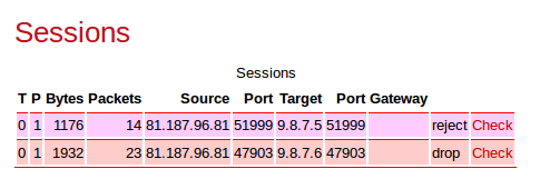
Note that drop and reject both drop packets, with the difference only being whether notification of this is sent back to the traffic source.
Tip
For a short period after startup the actions ofdrop and reject are treated as ignore.
This is so that a reboot which would forget all sessions allows sessions that have outbound traffic which is not NAT stand a chance of re-establishing by use
of outbound traffic. Without this delay, incoming traffic would create a drop/reject short lived session and could send an icmp error closing the connection.
This is configurable per rule-set.
Note
It is possible to mis-understand the function of the no-match-action attribute, given where it is specified (i.e. an attribute of the rule-set object).
This is particularly true when using XML. If you are unfamiliar with the FB2700's session rule specifications, you may interpret
the no-match-action as specifying what happens if the rule-set's entry-criteria are not met (i.e. at the beginning of processing a rule-set).
no-match-action specifies what happens after the entry-criteria were met, and all the rules were considered, but none of them matched ("no-match") i.e. at
the very end of processing a rule-set.
Caution
If all rule-sets have been considered, and no action has specified that the session should be dropped or rejected, it will be ALLOWED. The factory default rule-sets have a firewall rule with no-match-action set to drop to avoid this happening by mistake.
We recommend you use the firewall diagnostic tests to verify that you have constructed rule-sets and rules that provide the firewalling you intended. We also highly recommend external intrusion testing to verify behaviour. We also recommend that firewalling is done using the method described in Section 7.3.3.1.
This processing flow is illustrated as a flow-chart in Figure 7.2 :-
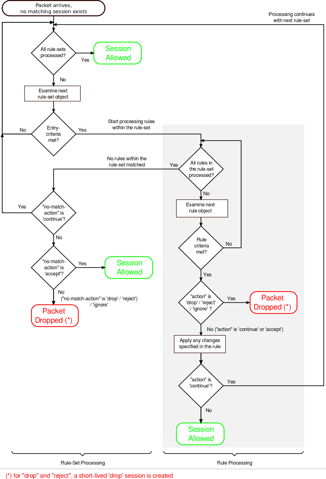
It is helpful to understand that a session rule contributes to the final set of information recorded in the session-table entry - a rule does not necessarily completely define what the session-table will contain, unless it is the only rule that matches the traffic under consideration. It is for this reason, that the rules contain attributes with names such as 'set-nat' - the 'set' refers to the action of setting a flag or a parameter in the session-table entry that is being 'constructed'.
It is possible, and quite common, for more than one rule (in different rule-sets) to match given traffic. In such cases, the rules generally serve different purposes - earlier ones might be for firewalling, whilst later ones might be used to subsequently assign some of the allowed-traffic to traffic-shaping. In such cases, an earlier rule will use the continue action to jump out of the earlier rule-set.
A rule-set is defined by a rule-set top-level object. To create or edit rule-sets in the web user interface, select the "Firewall" category icon
- here you will see the list of existing rule-set objects (if any), and an "Add" link next to each.
To create a new rule-set, click on an "Add" link to insert a new rule-set before the one associated with the link. This will take you to a new rule-set defintion. Editing an existing rule-set works similarly - click the "Edit" link next to the rule-set you want to modify.
As described in Section 7.3.2, a rule-set can optionally specify entry-criteria - in the web user interface, these come under the heading "Matching criteria for whole set", when editing a rule-set definition. The entry-criteria are detemined by the following attributes, all of which are optional, but if they are specified, then the criteria must be met for processing of the rules within the rule-set to occur. These are also criteria that can be specified on individual rules within a rule-set :-
- criteria regarding where the session is originating from :-
- source-interface : one or more interfaces
- source-ip : source IP address, or address range(s)
- source-port : source protocol port number, for protocols that use the port number concept e.g. TCP and UDP
- source-mac : (on individual rules) Only matches where from an Ethernet interface. Allows the source MAC if the initial packet to be checked for the initial bytes.
- criteria regarding where the target of the session is :-
- target-interface : one or more interfaces
- target-ip : target IP address, or address range(s)
- target-port : target protocol port number, for protocols that use the port number concept e.g. TCP and UDP
- general criteria :-
- protocol : the IP protocol number
There are also checks for just ip being either source or target IP, interface being either source or target interface.
Note
There is a special case for RFC5735 handling of source-ip and target-ip when they are specified as IPv4 and within 0.0.0.0/8-31. In this case the check is made for same network, so if you checked for target IP of, say, 0.0.0.0/24, that would pass if the target IP is within the same /24 as the source IP. This only works on IPv4, and only on subnets, not ranges, and only on source-ip and target-ip checks. Although not in RFC5735, the same logic is applied to IPv6 for ::/32-127.
A rule-set can also be named by setting the name attribute value, and enabled/disabled under control of a profile.
The comment attribute is a general purpose comment field
that you can use to briefly describe the purpose of the rule-set.
Under the heading "Individual rules, first match applies", you will see the list of session-rules within the rule-set. A session-rule is
defined by a rule object, which is a child object of a rule-set object.
Below the list of session-rules, you will see the no-match-action attribute, which is mandatory and has one of the values
shown in Table 7.2. Recall that this attribute
specifies the action to take if all of the rules in a rule-set have been considered, and none of them matched against
the traffic.
Although there are likely numerous ways in which you can construct workable rule-sets that implement firewalling in addition to any traffic-shaping or NAT etc., we recommend that you implement firewalling as follows :-
- create one or more rule-sets that are specifically for firewalling
- use one rule set per interface, with the interface specified as the target-interface in the entry criteria, such that the rule-set relates to sessions "to" that interface
- implement a 'default drop' policy on each firewalling rule-set, such that you have to list exceptions to this policy
to allow sessions to the specified target interface - to implement this policy, you set the
no-match-actionattribute to eitherdroporreject - ensure these firewalling rule-sets appear before any other (non-firewalling) rule-sets
- create subsequent rule-sets if necessary to perform any modifications to the session, such as NAT'ing, or to subject sessions to traffic shaping
Caution
If you have a large number of interfaces (for example, more than just WAN and LAN), you must take care that you have covered all the interfaces that need to be firewalled
Alternatively, you could have a single firewalling rule-set without any entry-criteria and with no-match-action
attribute set to either drop or reject - that way,
all traffic, regardless of its origin, or its characteristics, will be subject to the 'default drop' policy. A
disadvantage of this approach is that you will need to specify target interfaces in every rule in order to replicate the functionality of the
method described previously.
In any case, you can verify that your rule-sets function the way you intended using the diagnostic facility described in Section 16.1.
The XML fragment below shows a small firewalling rule-set for an interface, with a 'default drop' policy :-
 <rule-set name="firewall_to_LAN"
           target-interface="LAN"
           no-match-action="drop">
  <rule name="web"
        target-port="80"
        protocol="6"
        comment="WAN access to company web server"/>

 </rule-set>
Rule-set is named "firewall_to_LAN". The rule-set only applies to sessions targetting the "LAN" interface, from any other interface. The action to perform when no rule within the rule-set applies, is to "drop". | |
Rule is named "web", the criteria for matching the rule only specifies that the traffic must be targetting TCP (protocol 6) port 80.
The | |
If no rule matched the traffic, then the "no-match-action" of the rule-set is applied here - in this case the session is dropped, thus enforcing a 'default drop' policy. |
Note
The FB2700 itself does not generally need firewalling rules to protect against unwanted or malicious access, as the access controls on services can provide this protection directly - see Chapter 15 for discussion of access controls.
You may want to perform some outbound traffic filtering as well. This would normally want to work the other
way around to inbound filtering. With inbound you want to block all but those listed hence using
a no-match-action of drop. However, for outbound you will typically want to
allow all but those listed. To this end, you could create a rule-set for traffic from
inside interfaces, such as LAN and a no-match-action
of continue. Then include specific rules for those things you wish to block with an
action of reject.
Normally, a session table entry holds enough information to allow return traffic to reach its destination, without potentially being firewalled.
However, a session-rule can specify certain changes to be made to the outbound traffic in a session, and the session-table entry will hold additional information that allows the FB2700 to account for these changes when processing the return traffic.
For example, a session-rule can specify that the source IP address of the outbound packets be changed, such that they appear to be coming from a different address, typically one owned by the FB2700 itself. Return traffic will then be sent back to this modified address - assuming that the intention is that this traffic reach the original source IP address, the FB2700 will change the destination IP address in return traffic to be the original source IP address. It can do this because it has stored the original source IP address in the session table entry.
The set-source-ip, set-source-port, set-target-ip and set-target-port
attributes request this kind of change to be made.
Note
Theset-source-ip and set-target-ip value is normally a single IP address. However a range or prefix can be specified instead. If this is used then the IP that is set will be in the range/prefix but offset from the base depending on the offset withing the matching rule that matched the IP. This means matching in the rule and not the rule-set so may mean duplicating the matching source/target ip setting. E.g. if you match a /64 prefix, and then set a new IP with a /64 prefix, it will map to the same last 64 bits. This allows general prefix mapping, and allows things like NAT64 mapping a /96 of IPv6 space to all of IPv4 space, for example. If the set ip is an IPv4 range not a power of 2 prefix then the last 32 bits of the offset from the matching range is used, modulo the target range size.Note
Any rule that changes part of the "session" will affect the matching criteria in subsequent rule-sets and rules - i.e. they test the changed version of the session.
Quite separately to firewalling and session tracking, the FB2700 has to route traffic, and this is
done using normal routing logic (see Chapter 8).
The routing is done based on the destination IP address, as normal. However, it
can be useful for session tracking rules to override the normal routing. The set-gateway
allows a different IP address to be used for the routing decision, instead of the actual destination IP in the
packets. Setting this causes all subsequent packets matching the session to use that gateway IP for routing
decisions.
The set-graph and set-reverse-graph attributes cause the session traffic to be graphed, and therefore
possibly be subject to traffic shaping ; they perform the same function as the graph attribute that can be specified on many different
objects, as described in Chapter 10.
Each direction of the final established session can have a graph set. The normal set-graph
attribute sets the forward direction graph, and set-reverse-graph sets the reverse session
graph (remember, sessions have two sides).
Because of this, with set-graph, the graph "Tx" direction will be the direction in which the session was established, and the "Rx" direction is therefore
the opposite direction. With set-reverse-graph, the "Tx"/"Rx" directions are swapped compared to using set-graph.
There is also an option for set-graph-dynamic which causes the session to set a (forward) graph that is based on the MAC address of the source packet, if from an Ethernet interface, or the source IP. The graph is created if it does not exist. If set-graph is also defined then each new session created also causes the speed settings and long term shaper parameters to be copied from the named graph (in set-graph) to the MAC named graph being used. This is aimed at management of open WiFi and the like, allowing a named shaper to be defined and a copy of its settings created for each client based on MAC address.
As discussed in Section 7.2.1, each session-table entry has a timer associated with it - this ensures that inactive sessions are removed from the session-table. Two time-out values are configurable :-
- Initial time-out : this time-out period begins when the first reply packet of the session arrives at the FB2700 ; it is specified by the
set-initial-timeoutattribute. - Ongoing time-out : this time-out period begins when each subsequent packet of the session arrives at the FB2700 ; it is specified by the
set-ongoing-timeoutattribute.
Note
The actual timeout used is taken from a list of timeouts, and set to the next highest available value. The status/sessions list shows the timeout in force as well as useful flags for session started, and closed, and so on.- The session timeout is actually maintained separately for each direction, and only when the timeout happens in both directions does the session get dropped. This allows one-sided keep-alive packets as often used by protocols such as VoIP.
- The ongoing-timeout is set for both directions at once, only when both directions are considered to have started. The initial forward packet does not count as starting, but a further packet does. An ICMP error packet does not count to start a session either, and neither does a TCP packet that does not carry the ACK bit. These subtleties are designed to better handle unresponsive TCP endpoints and spoofed TCP packets even if allowed through the firewall.
- There are default timeouts for UDP, TCP, ICMP, and other protocols. For UDP the timeout also depends on the target port with port 80,443, and ports 1024 and higher getting a longer timeout as per RFC recommendations (see Table 7.1).
Session tracking rules can include an additional set of share records which define a choice of possible changes to make when setting up the session. This choice is normally random and based on a weighting for each choice.
This allows various forms of load balancing to be applied. E.g. you could port map to one of a set of web servers or mail servers.
Each share can also have a profile which can be used to exclude the option from the selection - this is typically tied to a ping or some other test to confirm the choice makes sense. In the example of web services being load balanced, a ping based profile could confirm each web server is actually up.
Normally the choice is random, but there is an option (hash) which can be set to make the choice determined based on a hash of the source and target IP address. This allows consistent mapping of sessions to the same server. As the choice depends on the set of servers which have an active profile, if the profiles change, sessions will get a new consistent mapping based on IP addresses.
It is possible for the creation of a session tracking entry to clash with an existing entry. This happens where the reverse session already exists. It cannot happen where the forward exists as in that case the traffic is mapped based on the existing session.
For example, if you had a session mapping traffic from an IP (A) port 5060 inside, to an IP (B) port 5060 outside, using NAT, so changing to be from the FireBrick's IP outside (C) random port to the target (B) port 5060, this creates two sides to the session, A->B one side, and B->C the other (reverse side), and allows traffic both ways.
Now, if you had a new session from outside (B) port 5060 to the FireBrick's IP (C) port 5060 which you want to map to (A) port 5060, you have a problem. The reverse (A) port 5060 to (B) port 5060 exists already, so the new session could not be created.
Normally, in the case of a clash with an existing session like this, the new session is not created. However, when the IPs are the same (in this example, A and C), and it is UDP, And the source port matches, then the original session is dropped and a new one created. This is primarily to assist NAT.
The other case where the existing is dropped and a new one created is were the existing clashing session is one sided, i.e. to drop or reject traffic.
The FireBrick supports protocols that allow devices on your LAN to request port mapping and firewall holes using RFC6886 (NAT-PMP) and RFC6887 (PCP). These are newer protocols than uPnP (universal plug and play) and used by many devices and applications. PCP is the later protocol and allows handling of IPv6 and also allows finer control such as opening a firewall hole for a specific block of external IPs only.
It is important to understand that there are two stages to the use of these protocols. Firstly a device on the local network will send a message to the FireBrick as the gateway device requesting a mapping or firewall hole. Secondly, a session may be created that matches that mapping or firewall hole, and needs to be allowed or not according to normal firewall rules.
The first stage is controlled by a setting on the subnet. By default, any subnet marked as nat="true" has pcp true as well, as does any subnet created using IPv6 Prefix Delegation. Settings on the interface and subnet can override these defaults. Only if a subnet has pcp set will a NAT-PMP or PCP packet be accepted and processed to create mappings.
Once created, the mappings can be viewed on the status page for sessions. When a new session starts it is checked against these mappings. The mappings may relate to incoming traffic or outgoing traffic. The mapping is applied to the new session, so, for example, incoming traffic to a specific mapped external port may be mapped to an internal device IP and port. This mapped traffic is then processed via the firewall rules as normal, but as it is already mapped it allows the firewall rules to consider the target (typically a private) IP address and port. This allows much finer control than would be possible otherwise, and one can, for example, easily allow all mapped traffic to specific internal devices such as gaming consoles.
In order to make the firewall rules easier to manage, any mapped traffic using a NAT-PMP/PCP rule will be flagged as pcp and so you can make rules relating specifically to these mapped sessions. As such a rule to allow all incoming mapped sessions is simple to create.
It is important to note that by default, on factory reset, the firewall rules block all incoming sessions to the LAN, and this will mean that even mapped sessions set up using NAT-PMP or PCP will also be blocked. An additional rule is necessary to allow such sessions. This rule can test for destination IPs even where these are private IP addresses on the LAN as the mappings are already applied before checking firewall rules. This means the FireBrick can be set to allow NAT-PMP and PCP sessions only for specific devices, ports and protocols by using firewall rules.
Tip
The factory default config has a rule that is set to disabled profile. Simply changing this to not have a profile will allow all mapped traffic into your LAN.Note
NAT-PMP and PCP have no authentication. Any device on your LAN can send a message to create mappings. Whilst the FireBrick does not allow the PCP third party option, it is possible for packets to have spoofed IP and even MAC addresses to open ports to other devices. As such a blanket acceptance of all mappings is a security risk, and ideally you should consider which mappings you wish to apply.Note
NAT-PMP and PCP can set up outgoing connections as well as incoming. These would typically be allowed through a firewall, but this allows long timeouts, so for example a long timeout outgoing UDP session could be created that then allows traffic back the other way for way longer than might otherwise have been expected. Obviously firewall rules can be used to check outgoing NAT-PMP/PCP sessions and these can even override the timeouts requested by NAT-PMP/PCP.Tip
With pcp allowed on a subnet you can see what mappings are created, and then carefully decide which mappings you wish to allow in firewall rules.Network Address Translation (NAT) is the general term used for sharing one IP address between multiple devices. It is typically a feature of broadband routers that are designed to operate with one external IP address and private (RFC1918) addresses on the inside (such as 192.168.x.x).
In additional to NAT, there are several ways in which one can do various types of port mapping and IP mapping which are described in the general session tracking and firewalling rules above. However, NAT is, itself, a complex issue and this section describes some of the issues and recommendations for how best to use NAT on a FireBrick.
NAT breaks the way Internet Protocol was designed as it stops end to end addressing and routing of packets. This causes problems with all sorts of protocols that sensibly expect IP to work as designed, and even some that assume NAT is in use. NAT is not itself a consistent and predictable process, and so it makes it very difficult to accommodate during protocol design.
Because of the many issues with NAT it is strongly recommended that NAT is only ever used where it is unavoidable. This is specifically where the availability of public IP addresses is limited.
Unfortunately with legacy IP version 4 addresses the supply of address space is now limited and most ISPs are only providing a single IPv4 address with an Internet Connection (or charging where more are provided). This means that it is common to require NAT for IPv4 on a typical Internet connection.
Tip
It is strongly recommended that you make use of PPPoE to connect to such an Internet connection, thereby affording the FireBrick itself with the single public IPv4 address assigned to the connection. This allows a number of features to work without use of NAT, including DNS relay, VoIP, and other internal operations of the FireBrick (e.g. clock setting, s/w updates, etc).Note
There is never any excuse to use NAT with IPv6. There is a virtually unlimited supply of IPv6 address space and you should have no problem obtaining necessary IPv6 address space from your ISP (assuming they do the current Internet Protocol, which is version 6). Remember, NAT is not a means of protection - the FireBrick has a firewall for that, NAT is a workaround for IP address sharing, something that is simply not necessary with IPv6 and should not be encouraged.Because of the many problems with NAT and the ways in which many protocols are broken by its use, many NAT devices (such as broadband routers) will provide an Application Layer Gateway (ALG) as part of the NAT implementation. This provides special case handling for each higher level protocol or system making use of NAT that the device knows of, and provides work-arounds for the issues caused by NAT. In some cases this may simply be customised session timeout, but in some cases the support can be extensive and make major changes to the payload of packets passed through the device.
ALGs have a number of problems. Obviously they only work at all where the device knows of the protocol in question, and this is a major drawback for new protocol development. However, they are often imperfect in the way they work. It is not uncommon for ALGs designed to support VoIP using SIP to be significantly flawed such that you are better off turning off the ALG and leaving end devices to work around the NAT themselves.
The real solution to all of the issues with NAT is not ALGs, as they are simply not a scalable work-around for problems. The solution is the use of IPv6, the current Internet Protocol version. The FireBrick is designed from the ground up to support IPv6 and we recommend the use of IPv6 wherever possible.
Note
The FireBrick provides no ALGs whatsoever for any form of NAT or IP/port mapping. This is a deliberate policy decision. However, there are a number features in the FireBrick that allow the correct operation of many protocols. These include the FireBrick SIP VoIP PABX server which allows it to act as a proper SIP gateway between locally connected (e.g. on RFC1918 addresses) and external SIP devices using the external IPv4 on PPPoE. The FireBrick also uses RFC recommended session timeouts for UDP when NAT is applied to allow many protocols to continue to work with minimal keep-alive packets. The use of customised session timeouts and port and IP mapping in the firewalling rules also allow for special cases to be accommodated where necessary. In addition, support for NAT-PMP and PCP allow port mapping and firewall holes to be created by devices on your network to allow NAT traversal for devices that use these protocols (sucessors to uPnP).The rules for firewalling allow a set-nat setting to be set true or false. Rules in later rule-sets can override this setting just like any other setting in the firewall rules.
Note
The setting of the NAT flag causes NAT to be applied, and this will change the source IP and port used for the session. However, unlike the explicit setting of a source IP or port in a rule, which causes the next rule-set to see the new changed setting, the NAT setting does not actually make these changes until the end of the processing of the rule-sets. i.e. a subsequent rule-set or rule cannot test the new source-ip or source-port that NAT will apply.What the NAT setting does is cause the FireBrick to change the source IP and port used for the session. It picks an IP based on the interface to which the traffic will finally be sent, and uses the most appropriate IP address that it can to try and ensure correct return traffic to that IP address.
The port that is chosen is picked from a pool of available source port addresses that are not currently in use. This ensures that the reply traffic can be correctly matched with the specific session even if multiple sessions are using the same original ports.
Note
It is possible to set the NAT attibute but also to explicitly set the source IP to be used. This will still allocate an available port, but will use the chosen source IP address. Care must be taken to ensure that the IP chosen is one that will allow the return traffic to be routed via the FireBrick to allow the NAT to be reversed.When using a PPPoE connection you may have a single IPv4 address assigned to the connection and so will need to NAT traffic sent down that connection to the Internet. To accommodate this there is a nat setting which can be enabled on the PPPoE configuration.
If this NAT setting is enabled then the default for all IPv4 traffic directed to the PPPoE session is for NAT to be used. This default applies if the firewalling rules have not otherwise explicitly set the NAT setting for the traffic in question. i.e. this can be overridden by specific firewalling rules.
Note
The NAT setting on PPPoE will not cause NAT to be set for IPv6 traffic.Tip
It is possible, of course, to use rule-sets and rules to control exactly when NAT applies rather than using the NAT setting on the PPPoE config. However, if the PPPoE connection only has one IPv4 address assigned, as is often the case, then setting NAT on the PPPoE config is usually the simplest way to achieve the configuration.Just as with PPPoE, there is a NAT setting which will cause traffic sent via the dongle to have NAT set by default, unless overridden by firewall rules. However, in the case of a dongle it is so rare to have a block of IPv4 addresses the NAT setting is enabled by default in the dongle configuration.
Note
The NAT setting on a dongle will not cause NAT to be set for IPv6 traffic.Tip
It is possible, of course, to use rule-sets and rules to control exactly when NAT applies rather than using the NAT setting on the dongle config. However, if the dongle connection only has one IPv4 address assigned, as is usually the case, then setting NAT on the dongle config is usually the simplest way to achieve the configuration.Where NAT is needed for other types of external routing, you can set NAT using explict rule-sets and rules. A simple rule-set at the end of all rule-sets can easily be set up to identify traffic being sent to a specific target interface and set the NAT setting.
Tip
It is recommended that you use PPPoE where possible rather than an external router which may additionally perform an additional layer of NAT.In some cases you may have a combination of real routed IPv4 addresses and some RFC1918 private addresses. These could be on different interfaces and subnets.
Typically in such cases you want to use NAT for external communications only when using the private addresses, but non-NAT when using the public addresses. The logic can be complicated where there may be fallback arrangements, such as a dongle, which may have to use NAT for all traffic even the normally public routed addresses if the dongle does not have routing for these addresses.
The recommended way to handle this is a rule-set at the end of rule-sets for handling NAT, in which a specific rule is created to match traffic being sent to the external interface (e.g. PPPoE) which is from an RFC1918 address and setting NAT mode in such cases. Using this arrangement ensures that traffic internally between RFC1918 and public IP addresses can continue without using NAT internally.
Tip
For fallback arrangements such as a dongle where all traffic needs to use NAT, simply set the NAT mode on the dongle configuration. This saves having more complex rule-sets to handle the fallback case.Carrier grade NAT (CGN) is where an ISP provides end users with a private address and provides a further level of NAT in the network (within the carrier).
Ideally you should try and make use Internet connections without CGN, but if you have to then you are likely to encounter additional issues with NAT. CGNs do often include some ALGs, but they bring all of the issues with NAT to a new level. As ever we recommend using PPPoE to avoid an extra layer of NAT in a broadband router.
In some cases the FireBrick may be expected to provide a carrier level of NAT in terms of number of sessions handled. Whilst the FireBrick does not have any ALGs, it can be very effective, and it supports overloading of ports. This means that the allocation of ports for NAT allows multiple sessions that are to different target IP addresses and ports to come from the same port on the FireBrick, allowing use of the same port multiple times. This allows a lot more sessions that would otherwise be expected based on number of TCP and UDP ports available. This overloading of ports is automatic and part of the way the FireBrick handles NAT.
For backwards compatibility with older FireBricks there is a NAT setting on the subnet config. The idea is that a subnet defined as an RFC1918 private block can simply be tagged as NAT. The effect is that any traffic from that subnet has NAT set by default. Again, this can be overridden by firewall rules.
Tip
The problem with this method is that all traffic from the subnet is NAT, even if to another subnet on the same FireBrick, and this is often not the case. This can be useful in very simple configurations where the FireBrick only has the one private subnet, but in most cases it is better to set NAT on a PPPoE or dongle interface and not use the NAT setting on the subnet configuration.Table of Contents
The routing logic in the FB2700 operates primarily using a conventional routing system of most specific prefix, which is commonly found in many IP stacks in general purpose computers and routers.
Conventional routing determines where to send a packet based only on the packet's destination IP address, and is applied on a 'per packet' basis - i.e. each packet that arrives is processed independently from previous packets.
Note that with this routing system, it does not matter where the packet came from, either in terms of source IP address or which interface/tunnel etc. the packet arrived on.
The FB2700 also implements more specialised routing logic that can route traffic based on other characteristics, such as source address, that can be used when routing based on destination IP address alone is insufficient. This is linked into the session tracking logic (see Chapter 7).
A route consists of :-
- a 'target' specifying where to send the packet to - this may be a specialised action, such as silently dropping the packet (a 'black-hole')
- an IP address range that this routing information applies to - the routing destination
A routing table consists of one or more routes. Unlike typical IP stacks, the FB2700 supports multiple independent routing tables.
Routing destinations are expressed using CIDR notation - if you are not familiar with this notation, please refer to Appendix B for an overview. Note that ip-groups cannot be used when defining subnets or routes. IP-groups allow arbitrary ranges and not just prefixes, but routes can only use prefixes.
There are two cases that deserve special attention :-
- A routing destination may be a single IP address, in which case it is a "/32" in CIDR notation (for IPv4). The /32 part (for IPv4) or /128 (for IPv6) is not shown when displaying such prefixes.
- A routing destination may encompass the entire IPv4 (or IPv6) address space, written as
0.0.0.0/0(for IPv4) or::/0(for IPv6) in CIDR notation. Since the prefix is zero-length, all destination IP addresses will match this route - however, it is always the shortest-prefix route present, and so will only match if there are no more specific routes. Such routes therefore acts as a default route.
The decision of where to send the packet is based on matching the packet's destination IP address to one or more routing table entries. If more than one entry matches, then the longest (most specific) prefix entry is used. The longest prefix is assumed to be associated with the optimal route to the destination IP address, since it is the 'most specific', i.e. it covers a smaller IP address range than any shorter matching prefix.
For example, if you have two routes, one for 10.0.1.32/27 , and another for 10.0.0.0/8 (which encompasses 10.0.1.32/27), then a destination IP address of 10.0.1.35 will match the longest-prefix (smallest address range) "/27" route.
The order in which routes are created does not normally matter as you do not usually have two routes that have the same prefix. However, there is an attribute of every route called the localpref which
decides between identical routes - the higher localpref being the one which applies. If you have identical routes with the same localpref then one will apply (you cannot rely on which one)
but it can, in some cases, mean you are bonding multiple links.
Tip
You can show the route(s) that apply for a specific destination IP address or address range using the CLI command show route.
You can also see a list of all routes in a routing table using the CLI command show routes.
There is also a routing display on the Diagnostics control web pages.
A route can specify various targets for the packet :-
Table 8.1. Example route targets
| Target | Notes |
| an Ethernet interface (locally-attached subnet) | requires ARP or ND to find the device on the LAN to which the traffic is to be sent. |
| a specific IP address (a "gateway") | the packet is forwarded to another router (gateway) ; routing is then determined based on the gateway's IP address instead |
| tunnel interface such as L2TP, PPPoE or FB105 tunnels. | such routes are created as part of the config for the interface and relate to the specific tunnel. |
| special targets | e.g. the FB2700 itself, or to a black hole (causes all traffic to be dropped) |
These are covered in more detail in the following sections.
Whenever you define a subnet or one is created dynamically (e.g. by DHCP), an associated route is automatically created for the associated prefix.
Packets being routed to a subnet are sent to the Ethernet interface that the subnet is associated with. Traffic routed to the subnet
will use ARP or ND to find the final MAC address to send the packet to.
In addition, a subnet definition creates a very specific single IP (a "/32" for IPv4, or a "/128" for IPv6) route for the IP address of the FB2700 itself on that subnet. This is a separate loop-back route which effectively internally routes traffic back into the FB2700 itself - i.e. it never appears externally.
A subnet can also have a gateway specified, either in the config or by DHCP or RA. This gateway is just like creating a route to 0.0.0.0/0 or ::/0 as a specific route configuration. It is mainly associated with the subnet for convenience. If defined by DHCP or RA then, like the rest of the routes created by DHCP or RA, it is removed when the DHCP or RA times out.
Example: <subnet ip="192.168.0.1/24"/> creates a route for destination 192.168.0.0/24 to the interface
associated with that subnet. A loop-back route to 192.168.0.1 (the FB2700's own IP address on that subnet) is also created.
Routes can be defined to forward traffic to another IP address, which will typically be another router (often also called a gateway)
For such a routing target, the gateway's IP address is then used to determine how to route the traffic, and another routing decision is made.
This subsequent routing decision usually identifies an interface or other data link to send the packet via - in more unusual cases, the subsequent routing decision
identifies another gateway, so it is possible for the process to be 'recursive' until a 'real' destination is found.
Example: <route ip="0.0.0.0/0" gateway="192.168.0.100"/> creates a default IPv4 route that forwards traffic to 192.168.0.100.
The routing for 192.168.0.100 then has to be looked up to find the final target, e.g. it may be to an Ethernet interface, in which case an ARP is done for 192.168.0.100 to find the MAC to send the traffic.
There is logic to ensure that the next-hop is valid - the gateway specified must be routable somewhere and if that is via an Ethernet interface then the endpoint must be answering ARP or ND packets. If not, then the route using the gateway is suppressed and other less specific routes may apply.
It is possible to define two special targets :-
- 'black-hole' : packets routed to a black-hole are silently dropped. 'Silent' refers to the lack of any ICMP response back to the sender.
- 'nowhere' (also called Dead End) : packets routed to 'nowhere' are also dropped but the FB2700 generates ICMP error responses back to the sender.
The blackhole and nowhere top-level objects are used to specify prefixes which are routed to these special targets.
In the User Interface, these objects can be found under the Routes category icon.
When using BGP you can also define a network which is announced by default, along with any dead-end-community, and treated otherwise the same as nowhere.
For data links that have an Up/Down state, such as L2TP or FB105 tunnels, or PPP links, the ability to actually send traffic to the route target
will depend on the state of the link. For such links, you can specify route(s) to automatically create each time the link comes up - when the link goes down these routes are removed automatically.
Refer to Chapter 13 for details on how to achieve this via the routes attribute on the tunnel definition objects.
This can be useful where a link such as PPPoE is defined with a given localpref value, and a separate route is defined with a lower localpref value (i.e.
less preferred), and therefore acts as a fallback route if the PPPoE link drops.
The conventional routing logic described above operates using one of possibly many routing tables that the FB2700 can support simultaneously. Routing tables are numbered, with the default being routing table 0 (zero).
The various ways to add routes allow the routing table to be specified, and so allow completely independent routing for different routing tables. The default table (table zero) is used when optional routing-table specification attributes or CLI command parameters are omitted.
Each interface is logically in a routing table and traffic arriving on it is processed based on the routes in that routing table.
Tunnels like FB105 and L2TP allow the wrapped tunnel packets to work on one routing table and the tunnel payload packets to be on another.
It is possible to jump between routing tables using a rule in a rule-set.
Routing tables can be very useful when working with tunnels of any sort - placing the wrappers in one routing table, allowing DHCP clients and so on, without taking over the default route for all traffic. The payload can then be in the normal routing table 0.
A key feature of the FB2700 is the ability to bond multiple links at a per packet level. This feature is only enabled on a fully loaded model of your FB2700.
Bonding works with routing and shapers together. (See Chapter 10 for details of shapers.)
The basic principle is that you have two or more routes that are identical (same target IP prefix) and have the same localpref, so that there is nothing to decide between them. As described above this normally means one of the routes is picked.
However, where the two (or more) routes are the same type of interface, and there are shapers applied to those routes, then a decisions is made on a per packet basis as to which interface to used. The shapers are used to decide which link is least far ahead. This means that traffic is sent down each link at the speed of that link.
To make this work to the best effect, set the tx speed of the shapers on the links to match the actual link speed. E.g. for broadband lines, set the speed to match the uplink from the FB2700.
For L2TP use as an LNS, the graph created for each L2TP session has an egress speed automatically set based on the speed details sent on the L2TP connection. These can also be overridden by a RADIUS response. The effect of this is that multiple lines that are connected to the same LNS and have the same IPs routed to the lines will automatically per packet bond traffic down those lines.
The conventional routing logic described so far operates very much like any conventional router, with the addition of some handling for bonding and duplicate subnets.
However the FB2700 also allows the possibility of route overrides which control routing in more more detail. This feature is part of session tracking functionality, and so applies on a per-session basis (contrasting with the per-packet basis for the conventional routing). For details on sessions, and session-tracking, refer to Chapter 7.
When establishing a session it is possible to scan an ordered list of rules which can consider not only the target IP but also source IP, protocol, ports, and interfaces being used. The result is (typically) to set a routing target IP for the session (and possibly a routing table to jump between tables).
Note
The destination IP in the packet header is not modified - rather, an 'overriding' routing target IP address is stored in the session-table entry.
This is done for each direction on the session and remembered. This new target IP is then used on a per packet basis in the same way as above instead of the destination IP address of the packet. This is the same as set-gateway in the normal session tracking logic.
However, routing overrides are applied at the end of checking rule-sets and applied both ways, allowing, in effect, a set-reverse-gateway.
Tip
Because the route-override just sets a new target routing IP and does not allow you to set a specific tunnel or such, you may want to have a dummy single IP address routed down a tunnel, and then use route-override rules to tell specific sessions to use that IP as the gateway. Future software releases may provide a means to specify a tunnel as a routing gateway more directly.
Note
Route override logic was originally devised to allow routing for use with tunneling protocols, but they are usually better handled with much less configuration using routing tables. As such this feature is rarely useful, and probably not the configuration setting you are looking for (waves hand in front of your face).Table of Contents
Profiles allow you to enable/disable various aspects of the FB2700's configuration (and thus functionality) based on things such as time-of-day or presence/absence of Ping responses from a specified device.
A profile is a two-state control entity - it is either Active or Inactive ("On" or "Off", like a switch). Once a profile is defined, it can be referenced in various configuration objects where the profile state will control the behaviour of that object.
A profile's state is determined by one or more defined tests, which are performed periodically. If multiple tests are specified, then the overall test result will be pass only if all the individual test results are pass. Assuming the profile's state is Active, then when the overall test result has been 'fail' for a specified duration, the profile transitions to Inactive. Similary, once the overall test result has been 'pass' for a specified duration, the profile transitions to Active. These two durations are controlled by attributes and provide a means to 'filter' out short duration 'blips' that are of little interest.
An example of a test that can be performed is a Ping test - ICMP echo request packets are sent, and replies are expected. If replies are not being received, the test fails.
Profiles can be logically combined using familiar boolean terminology i.e. AND, OR and NOT, allowing for some complex profile logic to be defined that determines a final profile state from several conditions. When considering the state of another profile, it is the previous second's state that is considered - i.e. profile states are all updated in one go after considering all profiles.
By combining profiles with the FB2700's event logging facilities, they can also be used for automated monitoring and reporting purposes, where profile state changes can be e-mailed direct from the FB2700. For example, a profile using a Ping test can be used to alert you via e-mail when a destination is unreachable. The profile logic tests are also done based on the defined interval.
The current state of all the profiles configured on your FB2700 can be seen by choosing the "Profiles" item in the "Status" menu.
Tip
You can also define dummy profiles that are permanantly Active or Inactive, which can be useful if you wish to temporarily disable some functionality without deleting configuration object(s). For example, you can force an FB105 tunnel to be Down, preventing traffic from being routed through it. Refer to Section 9.2.4 for details.
In the web user interface, profiles are created and edited by clicking on the "Profiles" category icon. A profile is defined by a profile
top-level object.
The following timing control parameters apply :-
interval: the interval between tests being performedtimeout: the duration that the overall test must have been failing for before the profile state changes to Inactiverecover: the duration that the overall test must have been passing for before the profile state changes to Active
The timeout and recover parameters do not apply to manually set profiles (see Section 9.2.4)
and those based on time-of-day (see Section 9.2.2.2).
'General' tests are provided for the following :-
- FB105 tunnel state : the
fb105attribute lists one or more FB105 tunnel names (see Section 13.2) - if any of the specified tunnels are in the Active state, this tunnel-state test will pass - USB 3G dongle connection state : the
dongleattribute lists one or more 3G dongle names (see Section 14.1.1) - if any of the specified dongles are in the connnected state, this dongle-state test will pass - PPPoE connection state : the
pppattribute lists one or more PPPoE connection names (see Chapter 11) - if any of the specified connections are up, this pppoe-state test will pass - Routable addresses : the
routeattributes lists one or more IP addresses (full addresses, not CIDR prefix ranges) - only if all the addresses are 'routeable' - i.e. there is an entry in the routing table that will match that address - will this test pass. Refer to Chapter 8 for discussion of routing tables and the routing logic used by the FB2700 - DHCP addresses : the
dhcpattributes lists one or more IPv4 addresses (full addresses, not CIDR prefix ranges) or names - if any of the listed names or IPs has a current DHCP lease issued, then this test will pass - VRRP state : the
vrrpattribute lists one or more Virtual Router group membership definitions (see Chapter 17) by name - if the FB2700 is not the master device in any of these Virtual Routers, this test will fail - Port state : the
portsattribute lists one of more physical Ethernet ports. If any of these ports is up then the test passes.Tip
You can also control port state with a profile, so you could have a port come up if another port is down to create a fallback arrangement.
If more than one of these general tests is selected (corresponding attribute specified), then they must all pass (along with all other tests defined) for the overall result to be pass.
Time and/or date tests are specified by date and/or time objects, which are
child objects of the profile object.
You can define multiple date ranges via multiple date objects - the date test will pass if the current date is within any
of the defined ranges. Similarly, you can define multiple time ranges via multiple time objects - the time test will pass if the current time is within any
of the defined ranges.
Tip
Unlike other tests, the change of state due to a date/time test takes effect immediately rather than waiting for several seconds to confirm it is still Saturday or some such.Like time/date tests, a Ping test is specified by a ping object, as a child of the profile object.
At most one Ping test can be defined per profile - logical combinations of profiles can be used to combine Ping tests if necessary.
Note
A ping of IPv4 address 0.0.0.0 is a special case, which causes a ping of the gateway address.The tests described in the previous section are used to form an overall test result. Normally this overall result is used to determine the profile
state using the mapping Pass > Active and Fail > Inactive. By setting the invert attribute to true, the overall result
is inverted (Pass changed to Fail and vice-versa) first before applying the mapping.
You can manually override all tests, and force the profile state using the set attribute - a value of true
forces the state to Active, and false forces it to Inactive.
You can also configure the set attribute with a value of control-switch. This causes the profile to be set manually
based on a control switch which is not stored in the configuration itself. The switch appears on the home web page
allowing it to be turned on or off with one click. It can also be changed from the command line. You can restrict each switch to one or more specific
users to define who has control of the switch. This control applies even if the user has no access to make configuration changes as the switch is not
part of the config. The switch state is automatically stored in the dynamic peristent data (along with DHCP settings, etc), so survives
a power cycle / restart. The control switch uses initial as the initial state when first added to the config, but at start up it picks up the state of the stored state.
These profiles can be used as simple on/off controls for configuration objects. The following shows an example of two fixed-state profiles and one control switch, expressed in XML :-
<profile name="Off" set="false"/>
<profile name="On" set="true"/>
<profile name="IT-Support"
         comment="Allow IT support company access to server"
	 set="control-switch"/>
Note
The control switches ignore other tests, just like other manual settings, but can be combined withand, or and not
settings - these have the effect of forcing the control switch one way. E.g. if an and profile is off then the control switch
is forced off. If it is on then the control switch can be manually set on or off as needed.Note that the value of the invert attribute is ignored when manual override is requested.
If we add special case switched profiles that are used internally, these will be named starting with fb-, so it is best not to name your own profiles starting fb-.
An example of the ACME renewal control profile is given below.
Note
There is a special case where profiles can be used to interact with the ACME certificate management. Acontrol-switch profile which has fb- followed by the name of the CA certificate authority, e.g. fb-letsencrypt.org will be activated at the start of the validation phase, and deactivated at the end. This profile can therefore be used to change firewall rules, etc, to allow ACME access to validate the certificate. You can set invert to reverse the operation of the switch. Use with care.
As with many things in the FireBrick it is possible to script access to the control pages. The control profiles are a particularly useful example of this as it allows external scripts to control if a profile is active or inactive.
Obviously security is a concern, and it is possible to create a user allowed access only from some IP addresses, and even allowed NOBODY level access, but listed as a user allowed to set a specific control profile. This then allows a script using a username and password to control the profile from specific machines.
For example, setting a named profile:-
curl --silent --user name:pass 'http://1.2.3.4/profile?set=profilename'
And unsetting a named profile:-
curl --silent --user name:pass 'http://1.2.3.4/profile?unset=profilename'
Table of Contents
The FB2700 includes traffic shaping functionality that allows you to control the speed of specific traffic flows through the FB2700. The FB2700 also provides graphing functionality, allowing specific traffic flows to be plotted on a graph image (PNG or SVG format) that the FB2700 generates. Within the FB2700, traffic shaping and graphing are closely associated, and this is reflected in how you configure traffic shaping - in order to be able to perform traffic shaping, you must first graph the traffic flow.
Several objects in the FB2700's configuration allow you to specify the name of a graph, by setting the value of the
graph attribute. This causes the traffic flow that
is associated with that object (a firewall rule, an interface, or whatever the attribute is attached to) to be recorded on a graph with the specified name.
For connections that have a defined state, such as a PPP link, the graph will also show the link state history. Other information, such as packet loss and latency
may also be displayed, depending on whether it can be provided by the type of object you are graphing.
For example, the XML snippet below shows the graph attribute being set on an interface. As soon as you
have set a graph attribute (and saved the configuration), a new graph with the specified name will be created.
 <interface name="LAN"
            port="LAN"
            graph="LAN">
The graph is viewable directly from the FB2700 via the web User Interface - to view a graph, click the "PNG" or "SVG" item in the "Graphs" menu. This will display all the graphs that are currently configured - it is not currently possible to show a single graph within the web User Interface environment.
It is possible to access the graph data in many ways, using the URL to control what information is shown, labels, and colours, and also allowing graphs to be archived. See Appendix K for more details.
Note
You may find images shown for graph names that are no longer specified anywhere in the configuration. Over time, these graphs will disappear automatically.
Alternatively, the underlying graph data is available in XML format, again via the FB2700's built-in HTTP server. The XML version of the data can be viewed in the web User Interface by clicking the "XML" item in the "Graphs" menu, and then clicking on the name of the graph you're interested in.
Both directions of traffic flow are recorded, and are colour-coded on the PNG image generated by the FB2700. The directions are labelled "tx" and "rx",
but the exact meaning of these will depend on what type of object the graph was referenced from - for example, on a graph for an interface,
"tx" will be traffic leaving the FB2700, and "rx" will be traffic arriving at the FB2700.
Each data point on a graph corresponds to a 100 second interval ; where a data point is showing a traffic rate, the rate is an average over that interval. For each named graph, the FB2700 stores data for the last 24 hours.
Note
Specifying a graph does not itself cause any traffic shaping to occur, but is a pre-requisite to specifying how the associated traffic flow should be shaped.
Graphing relies on the FireBrick's internal clock and so graphs will not work reliably if the clock is not set for any reason. However, you can still set an object's graph
attribute and use it for traffic shaping.
Once you have graphed a (possibly bi-directional) traffic flow, you can then also define speed restrictions on those flows. These can be simple "Tx" and "Rx" speed limits or more complex settings allowing maximum average speeds over time.
You define the speed controls associated with the graphed traffic flow(s) by creating a shaper top-level object. To create or edit a shaper object
in the web User Interface, first click on the "Shape" category icon. To create a new object, click the "Add" link. To edit an existing
object, click the appropriate "Edit" link instead.
The shaper object specifies the parameters (primarily traffic rates) to use in the traffic shaping process, and the shaper is associated with the
appropriate existing graph by specifying the name attribute of the shaper object to be the same as the name of the graph.
You can define a shaper object and set the speed controls for that shaper, and then define the
graph attribute on something, e.g. an interface, to apply that shaper to the interface.
It is also possible, in most cases, to simply set a speed attribute on some object. This
creates an un-named shaper (so no graph) which has the specified speed for egress (tx). This is unique to that object
unlike named shapers which are shared between all objects using the same named shaper.
It is also possible to set graph and speed attributes to create a named
shaper with the specified speed, without having to create a separate shaper object.
If you set a graph attribute without a speed attribute or creating a
shaper object then that simply creates a graph without traffic shaping. Multiple objects can share
the same graph.
Graphs can sometimes be created automatically and may have speeds applied. For L2TP sessions the circuit ID (which may be overridden by RADIUS auth responses) is used to make a graph for the session.
If defining a shaper using the shaper object there are a number of extra options which
allow a long term shaper to be defined. A long term shaper is one that changes the actual speed applied dynamically
to ensure a long term usage level that is within a defined setting.
The key parameters for the long term shaper are the target speed (e.g. tx), the
minimum speed (e.g. tx-min) and maximum speed (e.g. tx-max).
The target speed is the maximum rate that should apply over a long term, but actual speed is set dynamically
between min and max rates.
The rate is initially set to the maximum. Actual usage below the target builds up credit. This credit is limited to allow a defined minimum burst time at the maximum rate. So if not used for a while the maximum rate can be used for the minimum burst time. However continued use at more than the target will accumulate over usage.
Once this credit is used up the rate starts to drop. It will drop all the way to the minimum set if necessary.
Once the over usage is cleared, but less usage or usage capped to below the target rate, the rate increases to the target rate.
Once a further credit is accumulated by lower usage than the target, and this is at a level to allow the minimum burst time at maximum rate, the rate increases to the maximum rate again.
Shapers can be shared between FireBricks with a common broadcast domain.
The interface to broadcast and listen on for sharing is set via the share-interface setting in the global cqm options.
Once that is configured then setting the share option on a shaper will combine its state with that of other FireBricks when calculating any damping required.
Note
Shared shapers are identified in the broadcast domain by their name, so this must be the same on all FireBricks participating in the share.
A packet that passes through the FB2700 can pass through multiple shapers, for example
- The ingress interface can have a defined shaper
- When the packet passes through session tracking, the two sides of the session tracking (forward and reverse) can each have shapers that apply.
- If the packet is carried via an L2TP tunnel of any sort, there can be an aggregate shaper for the tunnel (e.g. the broadband carrier). There can also be a class applied to the session which is an aggregate shaper for an arbitrary group of sessions (often used when reselling broadband).
- When passing through an L2TP tunnel, the session typically has a graph and shaper based on the circuit ID which is specifc to that session. This is important for bonding multiple sessions as it controls the levels of traffic sent via each session.
- Obviously traffic could come in via one L2TP tunnel and go back out via another, incurring yet another set of shapers as above.
- PPPoE links can also have a defined shaper, which is important when bonding multiple links as it is used to decide how much traffic goes via each link.
- It is possible to create a bonded gateway route where multiple routes exist for the same
target (typically a default gateway) and each route as a speed set, which is itself a shaper.
This is used to control how much traffic goes via each of the bonded routes.
(You simply create more than one
routeobject with aspeedorgraphsetting). - The egress interface can have a defined shaper
Each shaper tracks how far ahead the link has got with traffic that has been recently sent. This depends on the length of packets sent and the speed of the shaper. This is, essentially, tracking how much is likely to be queued at a bottleneck further on. The FB2700 does not delay sending packets and assumes something with a lower speed is probably queuing them up later.
This record of how far ahead the traffic is gets used in two ways:
- If the shaper is too far ahead, then packets are dropped, causing the link to be rate limited to the selected speed. Exactly how much is too far depends on the packet size, with small packets (less than 1000 bytes) allowed more margin than large packets. This has the effect of prioritising DNS, interactive traffic, VoIP, etc.
- Where there are two or more links with shapers a link is picked based on which is the least far ahead. This has the effect of balancing the traffic levels between multiple links based on the speed of each link exactly.
Table of Contents
The FB2700 can either operate as a PPPoE client or as a PPPoE endpoint Broadband Remote Access Server (BRAS). A client connection is typically used to connect to an Internet Service Provider, either via a suitable PPPoE modem, bridging router, or direct connection. The PPPoE BRAS functionality might be used by service providers to provide connectivity, acting as a gateway between a carrier network (e.g. Broadband or mobile carrier) and the Internet.
The typical usage is to use one or more ports on the FB2700 each connected directly to a suitable PPPoE device such as a bridging router.
The PPPoE device is usually very dumb and may not need any configuration at all. The FireBrick is responsible for logging in to the ISP using the PPPoE link, and the configuration for this is part of the FB2700's configuration and not the router. This makes it very easy to make use of spare routers, etc, without the complication of configuring additional devices.
It is possible to connect more than one PPP device to a single FB2700 port using an Ethernet switch. If you do this then you ideally need a switch that handles VLANs (see Appendix E if you are not familiar with VLANs) so that each router can be logically connected to a different interface on the FireBrick. It is also a good idea to have a switch that supports jumbo frames where the endpoint supports them (FTTC, FTTP, and via suitable modems BT 21CN and TalkTalk).
Note
This section contains information relating to access network services (such as DSL and Fibre-To-The-Cabinet) available in the United Kingdom. Although this information will not be directly applicable to services available in other countries, the concepts are the same - with appropriate knowledge of your ISP service, and suitable equipment, the FB2700 should work equally well with services that are available in other countries.
In the UK there are various types of DSL line and router than can be used. Any device that supports PPPoE can work with the FireBrick, but some options are only available with some devices, as listed below :-
- BT 20CN or 21CN lines can support PPPoE and PPPoA on the wire. This means you can use them with a PPPoE/A modem (such as a Vigor V-130) out of the box, or with a bridging router such as the Zyxel P660 configured in bridge mode. BT support baby jumbo frames too.
- Other carrier PPPoA lines only support PPPoA, in theory. In practice they also support PPPoE. This means you can use a PPPoE/A modem, or a bridging modem.
- TalkTalk lines support both PPPoA and PPPoE, and so can work with a bridging modem. They support baby jumbo frames too.
- BT FTTC lines come with a VDSL modem which supports PPPoE directly so no extra equipment is needed to connect to the FireBrick.
- BT FTTP lines terminate on an active NTE which supports PPPoE directly so no extra equipment is needed to connect to the FireBrick.
For other types of lines in the UK, or those in other countries, you need to know what they can do on the wire (PPPoA or PPPoE) and have a suitable modem/router to talk that protocol and convert to PPPoE on the LAN link to the FB2700. It seems most DSL routers will bridge PPPoE on the wire to PPPoE on the LAN, but few will act as a PPPoE access concentrator. The Vigor V-130 is one of the few that handle PPPoA on the wire and PPPoE link to the FB2700.
A significant benefit of the Vigor V-130 is that it works with no configuration on BT 20CN and 21CN lines as well as other carrier PPPoA lines and TalkTalk lines - you just plug it into the line and the FB2700 and it just works. There are also modems that work in bridged mode, and support baby jumbo frames allowing PPPoE through to the carrier BRAS with full size MTU.
For fibre to the cabinet (FTTC) and fibre to the premises (FTTP) service you connect the FB2700 directly to the service (BT supplied modem) with no extra equipment.
A PPPoE link is defined by a ppp top-level object. To create or edit PPPoE links in the web user interface, select the "Interface" category icon -
- under the section headed "PPPoE settings" you will see the list of existing ppp objects (if any), and an "Add" link.
For most situations, configuring a PPPoE link only requires that you specify the port
group name (see Section 6.2)
that the router/modem is connected to and the login credentials i.e.
username and password. The port group is specified via
the port attribute on the ppp object,
and credentials are specified via the username and
password attributes.
If you are connecting multiple routers/modems via a VLAN capable switch to a single FB2700 port, you will also need to specify the VLAN used for the
FB2700 to router/modem layer 2 connection - this is done by setting the value of the vlan attribute too.
As an example, if you you were to connect a single modem/router
directly to port 1 on your FB2700 (i.e. not using VLANs), and you had
decided to name the port group PPP_PORT then the
configuration needed, shown as an XML fragment, would be :-
  <port name="PPP_PORT" ports="1"/>
  ...
  <ppp port="PPP_PORT" eth="1" username="..." password="..."/>
Note
It is common to connect a port directly to a PPPoE modem - in this case it can be beneficial to configure theeth setting to that port as well. This causes the Ethernet port to be powered down briefly when the PPPoE link closes for any reason, and for the re-try (PADI) sending to start quickly when the link comes up. The port reset can work around a known bug in many bridging broadband modems when used with fixed IP services.You may also want to give the PPPoE link a name, by setting the name attribute - you can then reference the link in, for example, a profile (see Section 9.2.2.1).
There are a number of additional options (see below), but for most configurations this is all you need. It causes the FB2700 to connect and set a default route for internet access via the PPP link.
If your ISP negotiates IPv6 on the link, then a default route is set for IPv6 traffic down the line. If the ISP handles ICMPv6 prefix delegation then an IPv6 block will automatically be assigned to your LAN. If not, then you could manually configure the IPv6 prefix the ISP is providing. There are options to control which interfaces get automatic prefix delegations in this way.
Normally PPPoE operates with a maximum packet size of 1492 bytes - this is due to the 8 byte PPPoE header
that is used, and the normal 1500 byte payload limit of an Ethernet packet. The FB2700 includes an option to set the PPPoE MTU, so that when used with equipment capable of jumbo frames
(such as BT FTTC and FTTP services, and with appropriate ADSL bridging modems) this allows use of slightly larger frames to provide a 1500 byte MTU. To achieve this, simply set the mtu attribute
to a value of 1500. By default the tcp-mss-fix attribute is also set, which means when working with a smaller MTU such as 1492, any connections that try and establish 1500 byte links are adjusted
on the fly to be the lower MTU. This avoids problems with a lot of corporate and bank web sites that do not handle MTU and ICMP correctly. Typically your ISP will be doing this TCP fix for you as well.
Testing has been done which confirms setting mtu="1500" works correctly on BT FTTC and FTTP lines, as well as BT 21CN and TalkTalk lines via a suitable bridging modem (Dlink 320B).
Note
Testing using a Zyxel P660R in bridge mode confirms that BT 21CN ADSL lines will negotiate 1500 byte MTU, but it seems the Zyxel will not bridge more than 1496 bytes of PPP payload. If you select more than 1492 MTU and have problems it could be that some device connecting you to the access concentrator cannot handle the larger packets (such as a bridge or a switch). For this reason the default MTU is 1492.
The PPPoE protocol allows multiple services to be offered, and the service setting can be used to select which is available. This is rarely needed and should be ignored unless you know what you are doing. If specified, even as an empty string, then only matching services will be selected.
The name specified via the ac-name attribute is the name of the PPPoE endpoint (access controller). In some cases there may be a choice of endpoints and setting this causes one to be selected by name.
Again, this is rarely needed, and if specified will only match the name you specify. On some other carrier PPPoE lines, for example, you could select a specific LAC by name if you wanted to.
The PPP connection status, and PPP negotiation can be logged by setting the log attribute to a valid log target.
The log-debug will log the whole PPP negotiation which is particularly useful when debugging connection problems.
As discussed in Chapter 10, graphs allow you to visualise connections, in terms of their state, traffic rates and patterns etc.
By setting the graph attribute, you can cause the state of the line, data transferred each way, and current packet loss and latency to be recorded on a graph.
Once you are graphing the PPPoE connection, you can set traffic shaping to control speed (see Section 10.1.2). Alternatively,
a PPPoE connection is something you can set a speed limit on directly - setting the speed attribute will control the speed of traffic sent to
the Internet - this is mainly used when bonding PPP links.
As uplink/egress speed can be very important to manage bonded lines, a further setting of auto-percent can be set to a percentage, e.g. 95. If set then the Firebrick looks for a connection info string in the final CHAPS connect message for a string in the format of digits/digits and assumes the second sequence of digits is an uplink speed in bits/second. The percentage is then applied and the tx speed set. If the speed is also set, this acts as a cap not allowing speeds to be set higher by auto-percent. A silly low value for speed in the message will be ignored.
To configure the FireBrick as a PPPoE BRAS, you need to configure a
PPPoE link (similar to configuring a client) - either by defining a
ppp top-level object in the XML config or by using the
web user interface. PPPoE links can be created from the "Interface" category
icon under the section "PPPoE settings", where you can click to "Add" a new
link. The mode should be set to bras-l2tp.
When the FireBrick is acting as a server, you should also configure
the l2tp object to contain a suitable
incoming configuration. This is because the PPPoE
connections appear as if they've arrived via L2TP, so they have the same
options of local IP termination or relay via L2TP onwards to another LNS.
See Section 13.3.1 for more information about the
handling of incoming L2TP tunnels.
Note
Since the BRAS uses these "virtual" L2TP connections, many of
the options in the ppp object are ignored or not used to
configure the server. Instead you should configure the incoming PPPoE
connection using L2TP settings.
The BRAS can be associated with an L2TP incoming section by matching the
ac-name of the BRAS ppp entry with the remote-hostname
of the incoming L2TP entry. Note that when ac-name is specified on the
BRAS, the client must also be configured with a matching ac-name.
To avoid this, it's also possible to use the name element of the BRAS
ppp entry as this will be used for matching with the remote-hostname if
no ac-name is specified. This makes it possible to associate BRAS ppp and L2TP
incoming sections without needing to specify an ac-name on the client.
Note
If a remote-hostname is not specified for an incoming
section, then that configuration will match with all remaining BRAS entries, so make sure
that specific L2TP incoming sections occur first in your config file.
L2TP settings can be created from the web user interface by selecting
the "Tunnels" category icon and selecting "Edit L2TP settings". Select "Add
an incoming connection". You can specify various options such as
pppdns and the local-hostname (i.e.
the hostname reported by the BRAS).
A simple configuration using local authentication might contain:
  <ppp port="PPP_PORT" mode="bras-l2tp" name="bras-example"/>
  ...
  <l2tp>
    <incoming remote-hostname="bras-example" local-ppp-ip="..." pppdns1="...">
      <match username="..." password="..." remote-ppp-ip="..." />
      <match username="..." password="..." remote-ppp-ip="..." />
    </incoming>
  </l2tp>
More complex configurations might typically use RADIUS to decide whether the session is accepted and what settings should be applied, or might relay sessions down an L2TP tunnel.
Just like for the PPPoE client, the BRAS mode supports baby jumbo frame negotiation to allow full 1500 byte MTU operation (as described earlier).
If an interface is configured to work in PPPoE BRAS mode, then it can accept packets with an additional VLAN tag. This is passed as the NAS_PORT on RADIUS requests relating to the connection. The reply packets have the same VLAN tag added. Where the interface is set up on VLAN 0 (untagged) then the additional VLAN tag is only processed where there is not an interface or ppp setting for that specific VLAN configured.
Note
The FireBrick identifies TR-101 Agent Remote ID and Agent Circuit Id as called and calling identities. It also picks up Downstream line rate. These are standard in BT GEA FTTC/FTTP services.Table of Contents
MQTT is a protocol that is designed to allow IoT (Internet of Things) devices to communicate - for example smart light switches, sensors, and all sorts of home automation.
To communicate, these devices connect to a broker which acts as a hub / switchboard to relay messages. The FB2700 can operate as an MQTT broker, allowing your IoT devices to communicate in a typical home or office.
The FireBrick operates three separate brokers: An internal insecure MQTT broker (typically for local IoT); an internal secure MQTTS broker; and a connection to an external broker (MQTT or MQTTS). Messages received on these can be kept separate, or relayed to any of the other two. Internal operations of the FireBrick that generate messages can be configured to sent to one or more of these three brokers. Internal operations of the FireBrick that accept messages can be configured to only accept from one or more of these brokers.
Note
At present the FireBrick operates MQTT v3.1 but it is planned that it will offer v5 as well in future.As with any broker, there are limitations to the operation. As an embedded device, the FireBrick is designed to ensure reliable operation, and so has some specific limitations to its operation. However, as with any FireBrick feature, if these are a problem for your use case, please do let us know.
- Maximum message size (3000 bytes).
- Maximum connections (300), including connections which are idle but have state or retained messages.
- Maximum subscriptions per connection (200).
- Maximum messages in flight (10000), including retained and will messages.
- Messages accepted and handshake for QoS 1/2, but are all demoted to QoS 0 for sending. As TCP is used messages are normally reliably sent, but this limitation greatly reduces complexity and state. Please let us know if this is an issue.
- No retained state over reboot.
The FireBrick has some specific features which are not found in many brokers.
- Concurrent MQTT and MQTTS operation - which can be separate or allow messages between the two.
- Feature to expire session states after a period when not connected.
- Feature to expire retained messages after a period when not connected. Very useful if you use MQTT to provision and reconfigure devices as otherwise old retained messages can linger forever.
- Not yet, but MQTT/MQTTS client with option to relay/aggregate clients to an external server.
- Integration with internal FireBrick features (see below).
- Allows weaker ciphers (RSA negotiation rather the DH) as common on ESP8266 TLS builds (can be disabled).
- Mapping one message to another. Matching topic using
+and#in the same way as subscriptions match, and matching payloads using?and*pattern matching. The new topic and payload can be set. Allows multiple matches for one message to create more than one new message.
The FireBrick allows integration of MQTT with a number of internal operations.
Messages for internal operation all use a JSON payload an a topic starting FireBricks/tag or FireBrick/serial/tag. The exception is where a message is to be generated to send to some other device, e.g. a lighting control, where the message can be specified as a topic, a space, and a text payload.
A profile can be set with a topic, and a payload for on and off. This causes an MQTT message to be sent when the profile is activated or de-activated. You can set this to be treated as MQTTS, so not sent to MQTT clients (depending on configuration for relaying MQTT/MQTTS). You can also set this as a retained message.
To send a message you have to set the on or off payload, even if this is to be blank, as the message is only sent if the corresponding payload is set.
A profile can also be set to control-switch with mqtt-control set which allows it to switched over MQTT. The control message has a tag of profile and a payload of a JSON object with one or more Boolean fields with the field name being the name of the profile to be set.
More on this will be added in due course.
The plan is to report call states as they happen.
The plan is also to allow calls to be directed in certain ways by MQTT message.
Each DHCP pool can be set to report allocations and renewals via MQTT on a specified topic. This reports a JSON payload with details of the allocation.
Table of Contents
- 13.1. IPsec (IP Security)
- 13.1.1. Introduction
- 13.1.2. Setting up IPsec connections
- 13.1.3. Using EAP with IPsec/IKE
- 13.1.4. Using certificates with IPsec/IKE
- 13.1.5. Choice of algorithms
- 13.1.6. NAT Traversal
- 13.1.7. Configuring a Road Warrior server
- 13.1.8. Connecting to non-FireBrick devices
- 13.2. FB105 tunnels
- 13.3. L2TP tunnelling
- 13.4. Ether tunnelling
The FB2700 supports the following tunnelling protocols :-
- IPsec (IP security)
- FB105 lightweight tunnelling protocol
- L2TP
- ETUN (Ether tunnelling)
IPsec is an implementation of the IPsec protocol and IKEv2 key management protocol, as defined in various RFCs. This provides the means to authenticate and encrypt traffic sent over a public communication channel (such as the Internet).
L2TP client functionality enables tunnelled connections to be made to an L2TP server
Ether tunnelling provides a mechanism to tunnel layer 2 ethernet traffic between two devices, using the protocol defined in RFC3378.
Support for FB105 tunnels means the FB2700 can inter-work with existing FB105 hardware. FB105 tunnels can also be set up between any two FireBricks from the FB2x00 and FB6000 ranges which support FB105 tunnelling.
One of the uses of IPsec is to create a private tunnel between two places. This could be two FireBricks, or between a FireBrick and some other device such as a router, VPN box, Linux box, etc.
The tunnel allows traffic to IP addresses at the far end to be routed over the Internet in secret, encrypted at the sending end and decrypted at the receiving end.
IPsec can also be used to set up a VPN between a roaming client and a server, providing security for working-at-home or on-the-road scenarios. This usage is usually known as a Road Warrior connection. The FireBrick can be used as the server for Road Warrior connections; it cannot act as a Road Warrior client.
There are three main aspects to IP Security: integrity checking, encryption and authentication.
The purpose of integrity checking is to ensure that the packets of data when received are identical to when transmitted - i.e. their contents have not been tampered with en route.
There are a number of algorithms that can be used to implement integrity checking. They all use a key which is known only to the two ends of the communication. The key is typically a sequence of random-looking bytes, usually expressed in hex notation.
Integrity checking on its own does not stop someone snooping on the contents of the packets, it just makes sure that they are not tampered with on the way (as only someone with knowledge of the key could change the data without invalidating it).
The purpose of encryption is to change the data when it is sent so that nobody snooping on the packet can make sense of it. There are many different algorithms, offering different levels of security. Encryption similarly involves a key which is known only to the two ends of the communication.
IPsec provides two ways to encapsulate data - AH (Authentication Header) which integrity checks the packet data and also some of the header fields (IP addresses), and ESP (Encapsulation Security Payload) - which both encrypts and integrity checks the packet data.
Authentication is a mechanism for ensuring that the two end users of a communication channel trust that they are who they think they are. Neither encryption nor integrity checking alone can do this. To ensure that you are talking to the correct person and not someone else masquerading as them, and to be sure nobody else can read your communications, you need to be sure that keys used for integrity checking and encryption are only known to the two (real) endpoints. Authentication can help prevent a "Man-in-the-Middle" attack, where someone who knows the keys can set himself up between the two endpoints, and without their knowledge can masquerade as the other endpoint to each end. Note that a Man in the Middle can both read the data and modify it, without either of the endpoints being aware that this has happened.
Note
There is scope for confusion in the use of the term Authentication. It is sometimes also used to mean integrity checking, and indeed the "Authentication Header" (AH) should really be known as the Integrity Check Header!
Choosing and configuring the IPsec algorithms and keys, as well as any other required connection parameters for a link is a complex task and also has its own security implications as compatible parameters, including the keys, need to be established at both ends of the link while at the same time ensuring the keys remain accessible only to the two ends. If you use any form of communication to do this and that communication channel is not itself secure, you have potentially lost your link security. For this reason there is a protocol known as IKE (Internet Key Exchange) which automatically negotiates and selects algorithms, keys and other parameters, and installs them at each end of the link, using a secure channel between the two systems. The FireBrick supports version 2 of the IKE protocol (IKEv2). IKE uses Public Key Cryptographic mechanisms to select the keys to be used, using the Diffie-Hellman key exchange mechanism. IKE also performs authentication between the two link endpoints using for example X.509 certificates, pre-shared secrets or other methods such as those supported by EAP (Extensible Authentication Protocol). It is still necessary to install suitable certificates, secrets or methods, obviously, but the configuration is simpler and more secure.
An IPsec IKE connection is established in two logical stages; first a secure control channel for the IKE negotiation is set up, and the peers authenticate each other using this channel, and then algorithms and keys to be used to secure the IPsec data are negotiated and exchanged using the secure channel. The control channel remains open during the lifetime of the connection, and is used to test the connection status, to cleanly close the link down, and also to periodically regenerate the algorithm key data (which mitigates the possibility that a third party has managed to crack the keys currently in use). During the first stage, the peers agree on algorithms to be used for integrity checking and encrypting the control channel, and additionally on algorithms to be used to securely generate the required keying data. These are agreed by the originating peer making a proposal, referred to below as the IKE proposal and the responding peer then selects the best algorithms which it supports. A similar, separate, proposal (referred to below as the IPsec proposal) is used to select the algorithms to be used for the IPsec data channel.
IPsec can also be used in what is known as manual-keying mode. When used in this way, IKE is not used; system administrators at each end of the link need to choose and agree on the integrity and encryption keys to be used, using some private mechanism which they know to be secure, before the IPsec connection is configured. For example, the system administrators may already know each other, and may arrange to meet in private and exchange keying information (which they trust they will not divulge to anyone else), and then configure their FireBricks to use the agreed keys. This is not a recommended approach as it it relies on the system administrators choosing good (ie random and unguessable) keys and keeping them secure. It also provides no way to automatically regenerate the keys regularly.
To fully appreciate the mechanism of authentication, it is necessary to understand the concept of IKE Identities. Each end of an IPsec/IKE peering has an identity, and the purpose of the IKE authentication process is to establish the identity to the peer - ie prove to the peer that you are the identity you proclaim to be. An IKE identity can take one of a variety of forms - it may be an IP address (IPv4 or IPv6), an email address, a domain name or a key identifier. It is important to understand that these forms are, in a sense, notional - you do not have to actually be addressable using a particular IP to proclaim it as your identity, nor do you have to be contactable by an email address if that form is used, nor does a domain name need to be resolvable to your IP address (or, indeed, resolvable at all). This is not unlike the use of personal names, at least in the UK, where you do not have to use your official birth certificate name - you can use any name provided that you can prove that you are associated with that name.
Each end of an IKE connection authenticates itself to its peer by signing a block of data which includes its identity along with other connection-specific data. Depending on the authentication method, the signature is generated using a pre-shared secret, a private key associated with an X.509 end-entity certificate, or a key determined by an EAP exchange.
If a peer authenticates using a pre-shared secret, you trust he is who he says he is simply by virtue of his knowledge of the secret. With certificates the situation is more complex: a successful signature verification using a certificate simply proves that the peer has the private key associated with the certificate used. To accept the authentication you also need to trust the certificate - ie you need to believe that the certificate does indeed belong to the peer. One way to do this is to use a self-signed end-entity certificate - in this case your peer gives you a copy of his certificate in advance, and you choose to trust it on this basis. To avoid needing to install a separate certificate for every peer you may need to authenticate with, it is more normal to have a chain of trust - you elect to trust a certificate from a certificate authority (CA), and you then implicitly trust any certificates which have been signed by that authority using that certificate (and in turn any subordinate certificates signed by these) without needing to explicitly install any of them beforehand. In other words, you are trusting that the CA (and any intermediates) who issued the certificate checked that the intended owner was entitled to use the certificate before issuing it. A certificate includes various data items including the identity of the owner, so the final step in the authentication check using a certificate is to confirm that the certificate used is valid, and its owner identity matches the IKE identity claimed by the peer.
First, an IPsec configuration section needs to be added to the configuration if not already present, or edited if present. Select "Add: New: IPsec connection settings" or edit the exiting entry on the tunnel setup page.
There are some global parameters affecting all connections which can be set on the main IPsec entry.
The logging options log, log-error, and log-debug can be used to steer logging information which is not specific to a particular connection to a selected logging target.
The allow and trusted entries can be used to restrict IKE connections to particular IPs and/or IP ranges. An IKE connection request can potentially be received from any device, and setting up a connection involves some CPU-intensive calculations. The IKE implementation attempts to guard against the possibility of Denial-of-Service attacks from rogue devices requesting bogus connections by limiting the initial connection rate, but for added security allow and trusted settings are also provided. Connections from IPs in either of the two lists are always accepted, and those in the trusted list are processed at higher priority. If an allow list has been set, connection attempts from IPs not in the allow or trusted lists are not accepted.
There is also a Force-NAT option which will force the FireBrick to assume that remote devices on the list are behind NAT boxes. IKE has built-in NAT detection so this option is rarely needed. See the separate section on NAT Traversal for more details.
When IKE connections are negotiated, a selection of compatible algorithms and keys for integrity checking and encryption are negotiated. The initiating end of the connection provides proposals of various combinations of algorithms it is willing to use, and the responding end picks a suitable set. The IKE implementation has built-in default proposal lists, which are suitable for normal use, but for tighter control further proposals can be configured. An IPsec IKE connection consists of two separate communication paths - the IKE control security association, and the IPsec data connection, and these have separate proposals, which are configured using the Proposal for IKE security association and Proposal for IPsec AH/ESP security association sections. See the later discussion on algorithms for further details.
IKE Road Warrior connections provide the ability for users to set up a VPN for remote access to a network. When a client connects an IPv4 and/or IPv6 address and other network data are allocated and communicated to the client for the duration of the connection. The details are configured in a roaming pool section, which can be referenced from one or more IKE connection sections. The pool of IPv4 and/or IPv6 address ranges for allocation needs to be configured here, and optionally a list of addresses of DNS and/or Windows NetBios name servers (NBNS) can be configured. If the IP address(es) to be assigned are not fully addressable on the internet, and the client is to be given internet access in addition to access to the local server network, the nat option can be given to make the FireBrick perform network address translation on sessions initiated by the client.
Note that there is a restriction on the total number of IPs (both IPv4 and IPv6 combined) of approximately 65536 addresses - ie a single IPv4 range of /16, or a single IPv6 range of /112.
To set up a new IKE connection, select "Add: New: IKE connections" on the IPsec configuration page.
There are a large number of options available for configuring a connection, but the majority can usually be left at their default settings.
Three connection modes are currently supported: Wait provides a dormant connection, which will only be set up when the remote peer initiates the connection; Immediate provides a connection which the local FireBrick attempts to initiate immediately; On-demand provides a connection which is only set up when the local FireBrick detects that it has traffic to send over the tunnel.
A Wait-mode connection is useful when the remote IP is not known - for example when it may change if the remote device moves to a different network or is behind a NAT device. Road Warrior connections must be Wait-mode; other connections may use any mode. It is permissible (and common) to set both ends to Immediate-mode - IKE will happily allow the connection to be initiated by either end, and will close a duplicate connection if set up simultaneously by both ends.
The IKE connection type is AH or ESP. ESP is by far the most commonly used, as it provides both integrity checking and encryption of traffic. AH provides integrity cheecking only, so data is transmitted in plaintext. AH does provide a very slight extra level of security, as the IP addresses of the tunnel encapsulation packets are also integrity checked. However, this is (a) incompatible with usage over NAT and (b) rather illusory, as with IKE the whole connection is authenticated at set up time, so the remote peer is already known to be valid.
Algorithms and proposals are discussed in more detail below. Normally, these can be left blank causing the default proposals to be used. If required, the IKE proposal list and/or the IPsec proposal list can configured. Each consists of a list of names of proposals which have been configured under the top IPsec configuration section.
The FireBrick supports three authentication methods:
- Secret: (AKA pre-shared key, or PSK) A secret key is entered in the local configuration and the same key is set up in the peer's configuration
- Certificate: an X.509 certificate is used (see below for full details)
- EAP: the Extensible Authentication Protocol is used. This is currently only supported for peer authentication.
The auth-method setting specifies how the FireBrick authenticates itself to the peer, and the peer-auth-method setting specifies how the peer authenticates itself to the FireBrick. Note that the authentication of each peer to the other is performed independently, and need not use the same method - eg one may authenticate using a certificate and the other using a pre-shared secret or EAP. Common arrangements are for both to use the pre-shared key method, for both to use certificates or (typically for Road Warrior setups) for one (the server) to use a certificate and the other to use EAP.
IKE authenticates each end of a connection using the connection's IKE identity. The identity is chosen when configuring each end, and can be specified in different ways, using the following syntax:
- IP:ip-address : an IPv4 or IPv6 address (eg IP:123.45.67.8)
- FQDN:domain : a dot-separated domain (eg FQDN:firebrick.co.uk)
- EMAIL:email-address : an email address (eg EMAIL:fred@somewhere.com)
- KEYID:string : any unstructured string (eg KEYID:This is my IKE ID)
DOMAIN or DNS are also accepted as alternatives for FQDN, and MAILADDR, MAIL or RFC822 are accepted as alternatives for EMAIL.
It is common to use a peer's real IP address as its IKE ID, and to avoid repetition the ID can be specified in the form "IP:" (ie omitting the IP address) to use the actual IP address. Note that if an IP address is specified there is no requirement for it to actually be the real IP address - it is used solely for identification. Similarly, if the FQDN or EMAIL forms of ID are used there is no requirement for the domain or email address to actually be associated with the peer or even to exist at all.
If the prefix (IP:, FQDN: etc) is omitted in the identity, the FireBrick chooses the most appropriate type, based on the syntax of the identity used.
During the connection set up phase, these IDs are used to authenticate the two ends to each other. Each peer passes its ID to the other end of the connection, in an encrypted and signed form. On receiving an ID it is checked (a) to confirm that it is the expected ID and (b) to confirm that the signature is valid.
If auth-method is Secret, the secret option should be set to the required secret using a free-form text string of arbitrary length. Note that the usual guidelines when choosing passwords should be followed to reduce the chance of the secret becoming compromised; a long string is recommended. If peer-auth-method is Secret the peer-secret option should be set to the secret used by the peer for authentication, or may be left blank in the common case where the local and peer secrets are the same. If certificate-based authentication is used, the certlist and peer-certlist options can be used to specify which certificates are to be used, or may be left blank in which case the the FireBrick looks for any suitable certificate in its certificate store. The use of certificates is discussed further below. If EAP authentication is used the EAP details (usernames, passwords etc) must be specified elsewhere in the EAP configuration section of the FireBrick config under the top-level User Access Control tem. The query-eap-id flag can be set to determine whether the client's IPsec identity should be used as the EAP identity or the client will provide a separate EAP identity when queried. The default setting is true, indicating that a separate EAP identity will be requested. Some EAP clients may require this to be set to false.
The peer-ips item is normally set to the IP of the peer when this is known. It must be a single IP when the connection mode is Immediate or On-Demand, but for a mode Wait connection this may be left blank or specified as a permissible range. Note that in this case the identity the peer provides when it attempts to set up the connection will be used to select the matching configuration connection details. The local-ip is optional - if omitted the IP used by the peer to reach the FireBrick is used for a connection initiated remotely, and the FireBrick chooses a suitable source IP when it initiates a connection. You can also optionally specify an internal-ipv4 and/or an internal-ipv6 address. When specified, these addresses are used for the source address of the tunnelled packet when the FireBrick sends traffic it originates itself down the tunnel (unless the source address has already been specified by some other means). If these are not specified the FireBrick will use the tunnel's local-ip setting when appropriate.
Note that although obviously the tunnel endpoint addresses must be the same type of address (both IPv4 or both IPv6) the traffic sent through the tunnel may be IPv4, IPv6 or a mixture of the two.
Apart from Road Warrior connections, you must configure routing to specify which traffic the FireBrick should send out through the tunnel. The routing configuration uses the same style as used elsewhere in FireBrick configuration. A simple set of IPs and/or IP ranges can be specified in the routes attribute, or for more complex routing a number of separate route elements can be added to the tunnel config. Metrics and the routing tables to be used may also be specified. The blackhole option can be set to ensure that traffic to be routed down the tunnel is discarded if the tunnel is not up. If not set, the normal FireBrick routing rules could select an alternate inappropriate transmission path, thus compromising security.
A graph may be specified to monitor data through the tunnel. A speed may be set to rate-limit the traffic.
mtu can be used to specify a maximum MTU value for tunnelled packets. Packets longer than this size will be fragmented or rejected using the normal IP fragmentation mechanism before being encapsulated. Note that after encapsulation of a packet the resulting packet may become too large to transmit using the MTU of the path used to transmit the tunnel traffic, in which case the encapsulated packet will be fragmented as usual. In some situations (for example where there are poorly implemented intervening NAT devices) such fragments may be dropped. In this case, the mtu setting can be useful to reduce the maximum size of the inner packets, so the encapsulated packets do not themselves need to be fragmented.
tcp-mss-fix can be set to attempt to avoid fragmentation in TCP sessions, by adjusting the TCP SYN header so that the negotiated TCP MSS will fit in the tunnelled MTU.
log, log-error and log-debug can be used to steer IKE logging information which is specific to this connection to a selected logging target.
dead-peer-detect can be set to the period (in seconds) used between checks that the connection is still live (ie the peer is responding). It defaults to 30 for normal connections, and 0 (off) for Road-Warrior connections. lifetime can be set to the period required between rekeying. The default is 1:00:00 (1 hour). The FireBrick will renegotiate the connection shortly before it reaches this period since the last renegotiation. Note that if dead-peer-detection is set to 0 (off) a dead peer will not be noticed until renegotiation is attempted.
To set up a new manually-keyed IPsec tunnel select "Add: New IPsec manually-keyed connections" on the top-level IPsec setup page.
Select the required encapsulation type - either AH (providing just authentication) or ESP (providing authentication and/or encryption). Select the required algorithms and choose appropriate keys. The key lengths depend on the selected algorithm according to the following table:
Table 13.1. IPsec algorithm key lengths
| Algorithm | Bytes | Hex digits | Example |
| HMAC-MD5 | 16 | 32 | 00112233445566778899AABBCCDDEEFF |
| HMAC-SHA1 | 20 | 40 | 000102030405060708090A0B0C0D0E0F10111213 |
| AES-XCBC | 16 | 32 | 0F0E0C0D0B0A09080706050403020100 |
| HMAC-SHA256 | 32 | 64 | 000102030405060708090A0B0C0D0E0F101112131415161718191A1B1C1D1E1F |
| 3DES-CBC | 24 | 48 | 00112233445566778899AABBCCDDEEFF0011223344556677 |
| blowfish | 16 | 32 | 00112233445566778899AABBCCDDEEFF |
| blowfish-192 | 24 | 48 | 000102030405060708090A0B0C0D0E0F1011121314151617 |
| blowfish-256 | 32 | 64 | 000102030405060708090A0B0C0D0E0F101112131415161718191A1B1C1D1E1F |
| AES-CBC | 16 | 32 | 00112233445566778899AABBCCDDEEFF |
| AES-192-CBC | 24 | 48 | 000102030405060708090A0B0C0D0E0F1011121314151617 |
| AES-256-CBC | 32 | 64 | 000102030405060708090A0B0C0D0E0F101112131415161718191A1B1C1D1E1F |
Note that in the current implementation when using manual keying the same key is used for both incoming and outgoing traffic. The same keys and algorithms must be configured at the remote end of the link.
The above keys are examples only. To reduce the possibility that your link could be compromised by keys becoming known or guessed you should generate them using a source of random or pseudo-random data. On a Unix/Linux system the command xxd can be used in conjunction with the /dev/random file. For example to generate a 20-byte key the command would be:
xxd -len 20 -p /dev/random
You also need to configure an SPI (Security Parameter Index) for both the incoming and outgoing traffic. The SPI value is an integer from 256 to 232-1. These are configured as local-spi for incoming traffic and remote-spi for outgoing traffic. The local-spi uniquely identifies this IPsec connection, so must be distinct for all IPsec connections on this FireBrick. The current FireBrick implementation requires that the local SPI for manual connections to be in the range 256 to 65535. The local-spi must match the outgoing SPI of the far end of the link, and vice-versa.
Routing for manually-keyed IPsec connections is the same as for IKE connections as described above.
EAP is typically used in conjunction with certificates to authenticate a Road Warrior connection. The FireBrick can act as a Road Warrior server, and uses EAP methods to authenticate the clients. During the authentication process the client sends a user identity (typically a username) and an encoded password to the FireBrick, and the FireBrick checks the username/password combination is valid. The FireBrick would normally be configured to use a certificate to authenticate itself to the client. A single Road Warrior IKE connection item can support multiple clients connecting at the same time; each client will be dynamically allocated a different IP address. Each user should be given a separate EAP username/password entry.
EAP usernames and passwords are configured under the top-level User Access Control section of the config. Select Users icon on the config web edit page, and enter the required details under the section User access control via EAP. Currently two EAP methods are supported - MD5 and MSChapV2; at least one of these is normally supported by Road Warrior clients. Note that MSChapV2 is more secure than MD5, and is the most commonly used, though it is rather an arcane method with known weaknesses. The subsystem item in the EAP config should be set to IPsec.
Note
The EAP authentication process involves a number of interchanges between the client and server. These take place using the IKE control channel, so although at this stage the server does not yet know the identity of the client connecting (indeed it is the purpose of the EAP interchange to achieve this), the path to the client is secure and encrypted so a third party cannot snoop on the authentication.
The FireBrick IPsec/IKE implementation supports authentication of tunnel endpoints using X.509 certificates. The FireBrick may authenticate itself to its peer using a certificate and private key installed on the FireBrick, and similarly the peer may authenticate itself to the FireBrick using a certificate trusted by the FireBrick.
The FireBrick has an internal secure storage area for holding certificates and private keys. This is held separately from the main FireBrick configuration, and is managed through the UI by selecting the Certificates section in the Config menu. Certificates may be uploaded to the FireBrick, downloaded and deleted, and private keys may be uploaded and deleted. Note that, for security, it is not possible to download a private key once installed; the only use to which a private key can be put is to allow an end-entity certificate to sign data - in particular the IPsec/IKE authentication data payloads.
The FireBrick has an ACME client which allows it to install certificates automatically with a recognised public Certificate Authority. This greatly simplifies the process.
In most cases, all that is needed it to ensure the FireBrick can be accessed via port 80 on a public IP address using a proper public hostname. This is the hostname and ID used for the IPsec connection. Once you have done this, simply add the hostname to the acme-hostname field, and your email address in the acme-terms-agreed-email field, in the system config. This will cause an automatic ACME certificate issue using Let's Encrypt, adding private key pairs for the letsencrypt.org account and the domain and then adding the certificate and any intermediate certificates for IPsec (and HTTPS) to work.
Note
By putting your email address in theacme-terms-agreed-email field you are indicating that you agree to the terms and conditions of the Certificate Authority being used.
This may include publishing a list of certified domain names, and sending emails for changes of terms, etc.
ACME is an automated system for the issuing of X.509 certificates for HTTPS (and other) use. The FireBrick can work as an ACME client to obtain certificates and is preset to use Let's Encrypt's free certificate issuing service, and automatically renew certificates. You can change settings to use an alternate ACME server if you pefer.
Note
If you wish to load your own private keys, and allow ACME renewal of certificate, or install your own certificates you can do so as described below. For ACME to work the keys need to have a name in the same way as the automatically generated keys, i.e. one for the account with the CA, e.g.letsencrypt.org and one matching the hostname for the certificate name. If such keys exist then they are used instead of making new keys when requesting a certificate.
If you do not load your own keys, the FireBrick makes keys internally. You can disable automatic key generation by setting acme-keygen false.
When a certificate is installed on the FireBrick, a short local name must be chosen to accompany it. This name appears in the certificate store contents list but need bear no relation to the actual certificate identity. The local names are displayed on the UI certificate configuration page, and are also used to form the filename (with .pem or .crt appended) when downloading the certificate from the FireBrick. The local names can also be used if desired in the IKE connection certlist and peer-certlist items to select the certificates to be used for a specific connection.
The FireBrick allows HTTP and HTTPS access, however, it needs a certificate loading before you can enable HTTPS. If accessing via HTTP and not HTTPS, uploading a private key should only be done from a locally-connected device where the security of the connection can be guaranteed - ideally using a direct ethernet cable or possibly a secure encrypted WiFi link - as the key data is transmitted in the clear.
There are a number of different formats in use for holding certificates and private keys. The FireBrick accepts standard DER-format (binary) and PEM-format (base64 armoured text) X.509 certificates, and DER-format and unencrypted PEM-format private keys in raw or PKCS#8 form, as generated by utilities such as OpenSSL. PKCS#7 and PKCS#12 format certificates and certificate bundles are not recognized by the FireBrick; these should be split up into their component parts (eg using OpenSSL) before being uploaded to the FireBrick. Note that private keys must not be encrypted (ie should not need a passphrase to access them). Again, OpenSSL can be used to unencrypt and remove a passphrase from a private key before upload. When downloading a certificate from the FireBrick, DER or PEM format can be selected.
For use with IPsec/IKEv2 end-entity certificates must hold an RSA or DSA public key. Currently the FireBrick also only accepts RSA or DSA keys for CA certificates. This should not be a problem at present as the use of newer style public keys in certificates used for signing other certificates is uncommon, and can always be avoided if generating one's own CA certificate.
As mentioned above, part of the authentication of a peer using a certificate consists of confirming that the peer's IKE ID matches the ID recorded in the certificate. Certificates can hold identity information in more than one way, and cryptographic implementations do not always agree on how the identity should be stored. The FireBrick accepts the CommonName (CN) field of the Subject DistinguishedName for a KEYID-type ID, or, for IP, FQDN or EMAIL type IDs, any SubjectAltName field of the right type. A certificate usually holds some information regarding its purpose, and again there is not universal agreement among implementations on how this usage information should be checked. The FireBrick requires a certificate to be used for IPsec authentication to be marked as allowing use for digitalSignature or nonRepudiation, and a certificate to be used for signing certificates must be marked as allowing use for certificate signature.
For a FireBrick IKE connection which authenticates itself to a peer using a certificate, it is necessary to install a suitable end-entity certificate along with its associated private key on the FireBrick. Unless the certificate is self-signed the certificate(s) used as CAs to provide a trust chain must also be installed, though private keys are not required for these (and for security should not be installed). During the IKE authentication procedure the FireBrick sends a copy of the certificate identifying itself to the peer, and also sends the trust chain of certificate(s) used to sign the end-entity certificate. The peer does not need to have the end-entity certificate installed, but must have a CA certificate (usually the self-signed "root" CA) installed so that it can check the validity of the certificate. The private key for the CA certificate should be stored in a secure manner - not on the FireBrick, and ideally not on any machine with a permanent network connection - a memory stick is recommended. The CA certificate can have any suitable subject identity, and the end-entity certificate must have a CN or SubjectAltName which corresponds with the local IKE identity which will be used for the connection. For reliable interworking with other kit it is recommended that this is set using a FQDN (aka DNS) subjectAltName field. The certificate which the FireBrick will use to authenticate itself to the peer can be specified in the connection certlist item, using the short local name set when the certificate was installed. This can normally be left unset, however, as the FireBrick will then choose a certificate which matches the local-ID setting.
certlist, if set, should be the end-entity certificate identifying the local FireBrick, and peer-certlist, if set, should be a list of the certificates which provide the trust for authenticating the peer's certificate. These can normally be left unset, in which case the FireBrick will choose any suitable certificate matching the IKE local-ID for authenticating itself, and any certificate(s) in the store for providing the trust of the peer's certificate.
A FireBrick connection which expects its peer to authenticate using a certificate needs to have either the end-entity certificate or a CA certificate providing trust installed. If the peer-certlist item is not set, the FireBrick will use any suitable certificate in its store to validate the peer's certificate; if set (to a list of short local names), only those certificate(s) listed are acceptable.
Note that it is not obligatory to create and use a self-signed certificate. A large organization may have a master CA which has been signed by a CA authority, and which is trusted automatically by many devices which have a built-in set of root CAs. This master CA be used to sign a subsidiary CA, which is then used to sign the end-entity certificate to be used for IKE authentication.
The following types of algorithm are used:
- Integrity: used to perform integrity checking of the control or data channels
- Encryption: used to perform encryption of the control or data channels
- DHGroup: used to select the Diffie-Hellman group to be used to agree a mutually-agreed secret key
- PRF: A pseudo-random function used to generate further keying info from the Diffie-Hellman key (control channel only)
- ESN: A flag indicating whether extended sequence numbers are supported for the data channel
Manually-keyed connections do not have a control channel, and use only integrity and encryption algorithms.
Both integrity checking and encryption allow a choice of algorithms. When using IKE the default algorithm proposals are in most cases a good choice as they allow negotiation with the peer to choose the best mutually supported algorithms. The supported algorithms are as follows:
Table 13.2. IKE / IPsec algorithm proposals
| Name | Type | Channels | Preferred |
| null | Integrity | Control, Data | Not in default proposal |
| HMAC-MD5 | Integrity | Control, Data | |
| HMAC-SHA1 | Integrity | Control, Data | |
| AES-XCBC | Integrity | Control, Data | |
| HMAC-SHA256 | Integrity | Control, Data | Yes |
| null | Encryption | Control, Data | Not in default proposal |
| 3DES-CBC | Encryption | Control, Data | |
| blowfish | Encryption | Control, Data | Yes |
| blowfish-192 | Encryption | Control, Data | |
| blowfish-256 | Encryption | Control, Data | |
| AES-CBC | Encryption | Control, Data | Yes |
| AES-192-CBC | Encryption | Control, Data | |
| AES-256-CBC | Encryption | Control, Data | |
| none | DHGroup | Data | Yes |
| MODP-1024 | DHGroup | Control, Data | |
| MODP-2048 | DHGroup | Control, Data | Yes |
| HMAC-MD5 | PRF | Control | |
| HMAC-SHA1 | PRF | Control | Yes |
| AES-XCBC-128 | PRF | Control | Yes |
| HMAC-SHA256 | PRF | Control | Yes |
| ALLOW-ESN | ESN | Data | Yes |
| ALLOW-SHORT-SN | ESN | Data | Yes |
Control items can be specified in IKE-Proposal lists, and Data items can be specified in IPsec-Proposal lists. If an IKE connection does not have an explicit ike-proposals entry, two default proposals are offered to the peer. The first includes all the Control entries in the above table marked as preferred, and the second includes all the implemented entries apart from null. Similarly if no explicit ipsec-proposals entry is given, Data entries marked preferred are included in the first proposal, and all except null in the second. The IKE negotiation always picks the first acceptable proposal, so the default proposals will have the effect of selecting from the preferred algorithms if the peer supports them, and otherwise from all available algorithms. Note that the null algorithms are never chosen by default; they provide no security and should only be used for testing.
A Road Warrior server connection provides the ability for a number of remote clients to set up VPNs to the server dynamically. When each client connects, it is allocated its own IP addresses (IPv4 and/or IPv6) from a pool maintained by the server. Most Road Warrior clients expect the server to authenticate itself using a certificate, and authenticate themselves with a username/password using EAP. Note that the FireBrick connection can be configured as a Road Warrior server, but not as a Road Warrior client.
There are a number of considerations when configuring a connection as a Road Warrior server The following assumes the common certificate+EAP authentication setup:
- local-ID: The connection local-ID should be set to a suitable identification for the server. Clients may need to be configured with this name. It is recommended that the FQDN: form of ID is used, and the domain name of the FireBrick is an obvious choice here (though not mandatory).
- peer-ID: Leave this unset in order to allow connections from any client.
- Certificates: An end-entity certificate identifying the FireBrick should be created, along with its private key, and signed with a suitable CA certificate, as described earlier. Both certificates and the private key are installed on the FireBrick, and the CA certificate should be installed on any clients wishing to connect. The end-entity certificate should have a SubjectAltName setting matching the local-ID chosen above.
- IP pool: A roaming pool should be configured for use by the connection, and included in the connection
roaming-pool setting. Consideration should be given when choosing the IP addresses to ensure they do not clash with
other uses of the same address range, and to ensure external traffic destined for these addresses will get routed
to the FireBrick so it can be sent over the VPN. One of three methods is typically used:
Addresses of DNS servers and optionally NBNS servers which the clients should use should also be configured in the roaming pool.
- Use a range in private address space - eg 10.42.42.1-100. As these are not internet-routable, if the clients require internet access through the VPN, incoming sessions from the client should be NATed by the FireBrick. Set the nat option in the roaming pool to achieve this.
- Use a portion of a subnet already routed to the FireBrick (eg by your service provider) but not currently in use.
- Use a portion of a LAN subnet. Care is needed with this approach; the range chosen must not clash with the addresses of any devices in use on the LAN - in particular ensure the range will not be allocated by a DHCP server. Additionally, if devices on the LAN need to communicate with the remote clients, the proxy-arp option should be set on the LAN interface/subnet config so that the FireBrick will announce itself on the LAN for the client addresses. This method has the advantage that the remote clients will act as if they are LAN-connected devices, so routing/firewalling etc already set up for the LAN will also apply to the clients.
- Authentication: Set the auth-method to certificate and the peer-auth-method to EAP.
- Users and Passwords: Set up user/password entries under the EAP section in the top-level User Access Control section of the FireBrick config.
- Mode: The connection mode should be set to Wait.
An example of a Road Warrior connection xml config may be:
<eap name="arthur"
      password="CorrectHorseBatteryStaple"
      subsystem="IPsec"
      methods="MSChapV2"/>
<eap name="ford"
      password="JosephGodspell"
      subsystem="IPsec"
      methods="MSChapV2"/>
...
<ipsec-ike>
  ...
  <roaming name="natpool"
    ip="10.100.100.0/24"
    DNS="8.8.8.8"
    nat="true"/>
  <connection name="VPN service"
              graph="eap-[ip]"
              local-ID="FQDN:vpn.server42paradigm.co.uk"
              roaming-pool="natpool"
              auth-method="Certificate"
              peer-auth-method="EAP"
              query-eap-id="true"
              certlist="VPNcert"/>
</ipsec-ike>
The FireBrick IPsec implementation should be compatible with any IPsec IKEv2 implementation. Note that IKE version 1 is not supported. Older equipment may not support IKEv2 yet, in which case manual keying may be possible. Several vendors have released IKEv2 support only recently; it is worth checking with your vendor for firmware upgrades. The FireBrick is known to interoperate well with StrongSwan implementations, and with more recent OpenSwan implementations. Road Warrior connections are possible using iPhone/iPad running iOS 8.1.3 or later, and using Android devices with the StrongSwan app.
StrongSwan supports IKEv2 with a comprehensive implementation. Consider a tunnel between a FireBrick and a Linux system with the following setup:
- FireBrick has IP address 192.168.1.1, Linux system has IP address 192.168.2.2
- Use default algorithm proposals
- Pre-shared secret authentication with secret "Nobody will ever guess this!"
- FireBrick is providing connectivity for a local user subnet 10.1.1.0/24
- Linux system is providing connectivity for a local user subnet 10.2.2.0/24
- Traffic for destination subnet is discarded when link is not up
A suitable FireBrick xml config for this would be:
<ipsec-ike>
  <connection name = "StrongSwan IKE"
    local-ip="192.168.1.1" peer-ips="192.168.2.2"
    mode="Immediate"
    blackhole="true"
    auth-method="Secret" secret="Nobody will ever guess this!"
    routes="10.2.2.0/24" />
</ipsec-ike>
A corresponding /etc/ipsec.config connection entry would be:
conn FireBrick
  left=192.168.2.2
  leftsubnet=10.2.2.0/24
  right=192.168.1.1
  rightsubnet=10.1.1.0/24
  reauth=no
  auto=add
  leftauth=psk
  rightauth=psk
The secret should be entered in /etc/ipsec.secrets as follows:
FireBrick : PSK "Nobody will ever guess this!"
The Android OS releases up to and including the current (Lollipop) release do not support IKEv2 natively, but a Road Warrior VPN can be set up using the StrongSwan app.
To set up a client VPN connection on an Android device, perform the following steps
- The FireBrick connection should be configured as a Road Warrior connection, and client usernames and passwords should be configured, as described earlier, using certificate authentication for the FireBrick and EAP for the peers.
- Install the StrongSwan app on the Android device - this is a free app available from the Google app store.
- Download a copy of the server CA certificate to the Android device. The easiest way to do this is to access the FireBrick certificate config page using the Chrome browser on the device, and download the CA certificate using either the DER or PEM link. Chrome should automatically save the certificate in the device download area.
- Configure a new client VPN connection using the StrongSwan app. The gateway should be set to the FireBrick IP address or domain name. The Type should be set to IKEv2 EAP (Username/Password) and the username should be set. The password can be set now, or if left blank will be prompted for when the connection is opened. Untick the CA certificate Select automatically box and click on Select CA certificate. Select the IMPORTED tab to display previously downloaded certificates and select the server CA certificate. Click Save to save the VPN details.
- The VPN should now be available for connection.
Apple have only recently introduced support for IKEv2 on iOS (since iOS version 8.1) and it is currently somewhat incomplete with rough edges. There is not yet a way to configure an IKEv2 VPN using the device UI. A profile containing all the connection details must be prepared elsewhere and downloaded/installed on the client.
To set up a client VPN connection on an iOS device, perform the following steps
- The FireBrick connection should be configured as a Road Warrior connection, and client usernames and passwords should be configured, as described earlier, using certificate authentication for the FireBrick and EAP for the peers.
- A connection profile should be generated.
A script is available to do this as http://www.firebrick.co.uk/tools/make-profile which should
be downloaded and run locally on a Unix or Linux system or on Windows with Cygwin.
There are several parameters, many of which can be left as default values. Mandatory arguments
are the PEM file for the CA trust certificate used by the server, the server IP address
and the server and client IKE identities. The client EAP identity (username) can also be specified - it defaults
to the client IKE identity. Names used to identify the VPN on the client settings pages
can also be supplied. The client IKE identity may be freely chosen - the Firebrick RoadWarrior
server will accept any client ID, and it will be displayed in the FireBrick IPsec status information
and logging. Note that the server address should be entered as an IP address rather than a domain name
for reliable operation; iOS appears to get confused when looking up a domain if it receives multiple
IP addresses or IPv6 addresses. [Symptoms of this include being unable to connect at all for varying
periods of time, and connections dropping shortly after establishing, while appearing to still be
connected on the device.]
An example of a make-profile command (where we assume the FireBrick address is 192.168.42.42):
# Note that trailing backslash characters have been used below
# to split commands over multiple lines for readability.

./make-profile SERVER=192.168.42.42 \
  LOCALID=MyiPhone CA=paradigm-ca.pem SERVERID=vpn.server42.paradigm.co.uk \
  USERNAME=arthur PROFNAME="Server42 VPN Profile" VPNNAME=Paradigm iphone
Note that the SERVERID must be the same as used when making the server certificate, and the paradigm-ca.pem file must be the CA certificate used to sign the server end-entity certificate. - Once prepared the profile (iphone.mobileconfig) should be installed on the client. It can be sent as an email attachment or downloaded from a webserver using safari. The client iOS should recognize the profile and should prompt to confirm installation. At this point the user password is required; note that there is currently no way to change it once the profile is installed - it is not prompted for when the connection is opened.
- The VPN should now be available for connection.
Unfortunately there is no logging or diagnostics available on the iOS device. If the connection fails to establish, the FireBrick IPsec debug logging may be helpful.
Setting up manual keying under Linux is possible using the ipsec-tools utility. Care should be taken if the Linux system is running an IKE or IKEv2 daemon, as this may interfere with the manual kernel IPsec configuration using ipsec-tools.
Consider a tunnel between a FireBrick and a Linux system with the following setup:
- FireBrick has IP address 192.168.1.1, Linux system has IP address 192.168.2.2
- ESP encapsulation using HMAC-SHA1 authentication and AES-CBC encryption
- Authentication key 0123456789012345678901234567890123456789
- Encryption key 00010203040506070809101112131415
- Incoming SPI 1000, Outgoing SPI 2000
- FireBrick is providing connectivity for a local user subnet 10.1.1.0/24
- Linux system is providing connectivity for a local user subnet 10.2.2.0/24
A suitable FireBrick xml config for this would be:
<ipsec-ike>
  <manually-keyed name = "Linux Manual"
    local-ip="192.168.1.1" peer-ips="192.168.2.2"
    local-spi="1000" remote-spi="2000" type="ESP"
    auth-algorithm="HMAC-SHA1"
    auth-key="0123456789012345678901234567890123456789"
    crypt-algorithm="AES-CBC"
    crypt-key="00010203040506070809101112131415"
    routes="10.2.2.0/24" />
</ipsec-ike>
A corresponding ipsec-tools config file would be:
  flush;
  spdflush;

  add 192.168.2.2 192.168.1.1 esp 1000 -m tunnel
    -E rijndael-cbc 0x00010203040506070809101112131415
    -A hmac-sha1 0x0123456789012345678901234567890123456789;

  add 192.168.1.1 192.168.2.2 esp 2000 -m tunnel
    -E rijndael-cbc 0x00010203040506070809101112131415
    -A hmac-sha1 0x0123456789012345678901234567890123456789;

  spdadd 10.1.1.0/24 10.2.2.0/24 any
    -P in ipsec esp/tunnel/192.168.1.1-192.168.2.2/require;
  spdadd 10.2.2.0/24 10.1.1.0/24 any
    -P out ipsec esp/tunnel/192.168.2.2-192.168.1.1/require;
Note that rijndael is the name used by ipsec-tools for the AES algorithm.
The FB105 tunnelling protocol is a FireBrick proprietary protocol that was first implemented in the FireBrick FB105 device, and is popular with FB105 users for setting up VPNs etc. It is 'lightweight' in as much as it is relatively simple, with low overhead and an easy set up procedure, but it does not currently offer encryption. Although encryption is not available, the protocol does digitally sign packets, so that tunnel end-points can be confident that the traffic originated from another 'trusted' end-point. Where it matters, encryption can be utilised via secure protocols such as HTTPS or SSH over the tunnel.
The protocol supports multiple simultaneous tunnels to/from an end-point device, and Local Tunnel ID values are used on an end-point device to identify each tunnel. The 'scope' of the Local ID is restricted to a single end-point device - as such, the tunnel itself does not possess a (single) ID value, and is instead identified by the Local IDs in use at both ends, which may well differ.
The protocol works by wrapping a complete IP packet in a UDP packet, with the destination port number of the UDP packet defaulting to 1, but which can be set to any other port number if required. These UDP packets are referred to as the 'tunnel wrappers', and include the digital signature. As with any other UDP traffic originating at the FB2700, the tunnel wrappers are then encapsulated in an IP packet and sent to the IP address of the far-end tunnel end-point. The IP packet that is contained in a tunnel wrapper packet is referred to as the 'tunnel payload', and IP addresses in the payload packet are not involved in any routing decisions until the payload is 'unwrapped' at the far-end.
Payload packet traffic is sent down a tunnel if the FB2700's routing logic determines that tunnel is the routing target for the traffic. Refer to Chapter 8 for discussion of the routing processes used in the FB2700. Often, a dynamic route is specified in the tunnel definition, such that traffic to a certain range of IP addresses (or possibly all IP addresses, for a default route) is routed down the tunnel when it is in the Up state - see Section 13.2.4 for details.
Tip
Payload IP addressing is not restricted to RFC1918 private IP address space, and so FB105 tunnels can be used to transport public IP address traffic too. This is ideal where you want to provide public IP addresses to a network, but it is either impossible to route the addresses directly to the network - e.g. it is behind a NAT'ing router, or is connected via networks (e.g. a 3rd party ISP) that you have no control over - or you wish to benefit from having 'portable' public IP addresses e.g. you can physically relocate a tunnel end-point FB2700 such that it is using different WAN connectivity, yet still have the same public IP address block routed to an attached network.
You define a tunnel by creating an fb105 top-level object. In the web User Interface, these objects are created and managed
under the "Tunnels" category, in the section headed "FB105 tunnel settings".
The basic parameters for a tunnel are :-
name: name of the tunnel (OPTIONAL)local-id: the Local ID to use for the tunnel (REQUIRED)remote-id: the ID used at the far-end for this tunnel (this will be the Local ID used on the far-end for this tunnel) (REQUIRED)secret: this is a pre-shared secret string that must be set to the same value in the tunnel definitions on both end-point devicesip: the IP address of the far-end end-point device (OPTIONAL)
The far-end IP address is optional, and if omitted, tunnel wrapper packets will be sent to the IP address from which wrapper packets are being received (if any). As such, at least one of the two end-points involved must have a far-end IP address specified, but it is not necessary for both ends to specify the other. This allows you to set up a tunnel on an end-point without knowing (or caring) what the far-end IP address is ; this means you can handle cases such as one of end-points being behind a NAT router that has a dynamic WAN IP address, or can be used to simplify administration of end-points that are used to terminate a large number of tunnels, by omitting the far-end IP address in tunnel definitions on such 'shared' end-points. The latter case is typical where an ISP deploys a FireBrick device to provide a 'head-end' device for tunnel bonding.
If you wish to use a different UDP port number than the default of 1, specify the port number using the port attribute.
The status of all configured FB105 tunnels can be seen in the web User Interface by selecting "FB105" from the "Status" menu. The tunnels are listed in ascending Local ID order, showing the far-end IP in use, the tunnel name, and the state. The table row background colour is also used to indicate tunnel state, with green for Up and red for Down.
Note that there is a third state that a tunnel can be in, that is "Up/Down" - this indicates that tunnel wrapper packets are being received, but that they are informing this end-point that the far-end is not receiving tunnel wrapper packets. This means the tunnel is essentially only established unidirectionally, typically because of a firewalling, routing, NAT or similar issue that is preventing the correct bidirectional flow of tunnels wrapper packets between the tunnel end-points.
Tunnel status can also be seen using the show fb105 CLI command - see Appendix J.
Since a tunnel can only carry traffic properly when in the Up state, any traffic routed down a tunnel that is not Up will be discarded. The ability to dynamically create a route when the tunnel enters the Up state (and automatically delete the route when the tunnel leaves the Up state) allows the route to be present only when traffic can actually be routed down the tunnel. In combination with the use of route preference values, you can use this to implement fall-back to a less-preferred route if the tunnel goes down. Alternatively, you may want to intentionally use a different tunnel to carry traffic, and use profiles to enable/disable tunnel(s) - the dynamic route creation means that you do not need to manually change routing information to suit.
A dynamic route is defined by setting the routes attribute on the tunnel definition, specifying one or more routing destinations
in CIDR format, as discussed in Section 8.1.
Multiple FB105 tunnels can be bonded together to form a set, such that traffic routed down the bonded tunnel set is distributed across all the tunnels in the set. This distribution is done on a round-robin per-packet basis i.e. the first packet to be sent is routed down the first tunnel in the set, each subsequent packet is routed down the subsequent tunnel in the set, and the (N+1)'th packet (where N is the number of tunnels in the set) is again routed down the first tunnel. This provides the ability to obtain aggregated bandwidths when each tunnel is carried over a different physical link, for example, such as using multiple ADSL or VDSL (FTTC) connections.
Note
Using tunnel bonding to aggregate access-network connections such as ADSL or VDSL to provide a single 'fat pipe' to the Internet requires there to be another FB105 tunnel end-point device to terminate the tunnels. Ideally this 'head-end' device is owned and operated by your ISP, but it is also possible to use a head-end device hosted by a third party, or in a datacentre in which you already have equipment. ISPs that can offer tunnel-bonding for Internet access include Andrews & Arnold and Watchfront.
To form a bonded tunnel set, simply specify the set attribute of each tunnel in the set to be a value unique to that set. Although not required,
you would typically use a set value of 1 for the first set you have defined. You can defined multiple bonded sets by using different values of
the set attribute in each set.
If you are using NAT in your network, it may have implications for how to successfully use FB105 tunnelling. The issues depend on where (on what device) in your network NAT is being performed.
If you have a bonded tunnel set implementing a single logical WAN connection, then the FB2700 will typically have multiple WAN-side IP addresses, one per physical WAN connection. If you are using the FB2700 to NAT traffic to the WAN, the real source IP address of the traffic will be translated by the NAT process to one of the IP addresses used by the FB2700.
When this NAT'd traffic is carried via a tunnel, it will be the source address of the tunnel payload packet that is modified.
Whatever address is used, reply traffic will come back to that address. In order to ensure this reply traffic is distributed across the tunnel set by the far-end tunnelling device, the address used needs to be an address that is routed down the tunnel set, rather than one associated with any particular WAN connection.
In order to handle this scenario, the internal-ip attribute can be used to define which IP address is used as the source IP address of the tunnel
payload packets.
If you are using another device that is performing NAT (for example, a NAT'ing ADSL router) and that device is on the route that tunnel wrapper packets will take , you may have to set up what is generally called port forwarding on your NAT'ing router.
If the FB2700 is behind a NAT router, it will not have a public IP address of its own which you can reference as the far-end IP address on the other end-point device. Instead, you will need to specify the WAN address of the NAT router for this far-end address. Whether you need to set up a port forwarding rule on your NAT router depends on whether the FB2700 behind the router has a far-end IP address specified in tunnel definition(s), as follows :-
- If it does, then it will be sending tunnel wrapper packets via the NAT router such that a session will have been created in the NAT router by the session tracking functionality that is used to implement NAT (this assumes there is no outgoing 'firewall' rule on the NAT router that would prevent the wrapper packets from being forwarded). The established session will mean that UDP packets that arrive from the WAN side will be passed to the UDP port number that was the source port used in the outgoing wrapper packets.
- If it does not, then you will have to manually set up a port-forwarding rule, since there will have been no outbound packets to initiate a session.
The forwarding rule should specify the UDP port number that is being used by the tunnel wrapper packets (the
portattribute value in the tunnel definintion, or the default of 1 if the port is not specified)
Layer 2 tunnelling protocol is a standard way to pass IP packets via a tunnel. It was originally used for dialup connections, connecting the RAS (Remote Access Server) to the LNS (L2TP Network Server), and is still used today within Internet Service Providers for broadband connections. L2TP has the advantage that it is very standard and interacts with a variety of equipment.
The FireBrick provides a means to accept static L2TP connections with configured username, password, and IP routing.
The FireBrick also provides a means to make an outgoing L2TP connection as if it was a RAS, connecting to an LNS. This can be used with ISPs that offer this service, or could be used, for example, to connect to another FireBrick.
Note
Some systems may refer to L2TP when they actually mean L2TP over IPsec, which was used more commonly before IKEv2 was available in IPsec, and is not supported.L2TP is usually used by Internet Service Providers, but it can also be used to create point to point tunnels connecting, say, two FireBricks together to pass IP traffic. The configuration for this can be a little confusing because L2TP is designed for multiple connections over separate tunnels between Access Controllers and L2TP Network Controllers, so the protocol involves more than one layer and authentication, and a lot of detailed settings.
Once upon a time the Remote Access Server (RAS) would have had a bank of modems or ISDN links, but these days it would be broadband connections over PPPoE. A RAS would create tunnel to an L2TP Network Server (LNS). Once a call comes in, the RAS would then create a session over that tunnel connecting the LNS to the end user. Each tunnel can hold multiple sessions all to the same LNS. The LNS then talks PPP over the tunnel/session to the end user and negotiates login details and IP addressing and so on. It then uses PPP to pass IP packets allowing a connection to the Internet.
If you make a point to point link, one end acts as the RAS, and makes a tunnel to the other end acting as an LNS, and then it creates a session over that tunnel. The settings needed for this are often a lot simpler than an ISP would use, so there is a lot of the FireBrick configuration you can ignore. It is, however, useful to understand some of the terms and settings, especially the authentication.
The FireBrick uses a static configuration to decide if it will accept an incoming L2TP tunnel. This is the Incoming L2TP
configuration. An incoming tunnel has very few credentials - the main one being the hostname it sends. This
is matched against the remote-hostname (which allows a wildcard, even).
You can also match to allow specific RAS IP addresses, as well as the routing table used.
The secret needs to be the same on the RAS and LNS.
Once the first match is found, the L2TP tunnel can be accepted. Most of the remaining configuration settings are not related to the tunnel as such, but define the default settings for any session that comes in over the tunnel. These settings can normally be omitted as they will have sensible defaults anyway.
A single tunnel config allows multiple instances of that tunnel to be created. If you are making multiple connections you may want to create different tunnel hostnames to allow fine control of specific features.
Once the RAS has a tunnel to the LNS it can create a session. The FireBrick acting as the LNS has to decide to accept the session or not, and what settings to use for the session.
The FireBrick acting as an LNS can use a static configuration to accept a session, or use RADIUS. An ISP would typically use RADIUS which allows a separate authentication service to decide if to accept the session and the settings that apply.
The static configuration consists of match settings. These are part of the relevant Incoming L2TP
configuration for the tunnel being used.
The main criteria is username (which can be wildcard, even), but can also match calling-station-id
and called-station-id which would have once been phone numbers, but are typically some sort of circuit ID
and service ID in broadband. The password has to be correct, if specified. Making a point to point L2TP
link allows all of these to be set on the outgoing connection.
Having found the first match, there are a few settings which can be controlled. This is not the full set of session
settings, but most can be set as a default in the Incoming L2TP tunnel configuration if required on a point to point static configuration.
The main setting is remote-ppp-ip which defines the IPv4 endpoint for the far end. If this is set then the
session is accepted and routing for this IP is negotiated and routed. Additional routes can also be set.
If the remote-ppp-ip is not defined, then relay settings can be defined to allow
the session to be relayed down another L2TP tunnel. These include the hostname, IP, and secret to use.
If a profile associated with an incoming connection is disabled then existing connections will be allowed to persist, however no new ones can be established. This is useful if you need to gracefully drain a particular set of connections.
An outgoing L2TP connection means the FireBrick is wanting to establish a session with IP routing.
To do this it is necessary to create an L2TP tunnels first, so the outgoing configuration includes
details of both the tunnel (local-hostname, secret, server IP),
and the session (username, password, calling-station-id,
called-station-id).
If a tunnel exists with the right credentials, it is re-used, so having more than one session, although typically you do
not do this as tunnels to the same LNS will normally be via different routing tables and backhaul links. If no tunnel
exists, one is created first and then the session created over that tunnel. If the session drops, it may be re-established
over the same tunnel. If the tunnel drops (which drops all sessions in it) then it hangs around for a few seconds before
a new tunnel can be made (fail-timeout).
Note
The config makes use of prefixes likelocal-… and remote-…. These are relative to the device you
are configuring. So a config to link two FireBricks will have local-hostname one end matching the
remote-hostname the other. Similarly settings like tx-… and rx-…
are relative, tx being transmit/send from this device, and rx being receive to this device.
Note
As with other tunnels, it is often useful to set the payload table to a different routing table to the tunnel traffic, to avoid sending tunnel traffic down the tunnel. This is particularly important for an outgoing tunnel as the default is to route all traffic (i.e. 0.0.0.0/0 and ::/0) down the tunnel when connected. You can configure specific routes to be passed down the tunnel if you wish. Routing in to this tunnel depends entirely on the configuration at the other end.Tip
The debug level logging is ideal for showing the details of the low level connection and PPP negotiation. This is recommended when first setting up such tunnels, and should be checked at both ends to identify any errors or problems.Ether tunnelling provides a mechanism to tunnel layer 2 ethernet traffic between two devices, using the protocol defined in RFC3378.
An ETUN tunnel provides a link layer 2 connection between two specific physical ports on different FireBricks. Consider two FireBricks A and B which are able to communicate with each other using IP (eg over the internet). An otherwise unused port on each FireBrick can be configured as an ETUN port. Every ethernet packet arriving at FireBrick A's ETUN port is encapsulated and transmitted to FireBrick B (over IP). FireBrick B decapsulates the packet and transmits it on its configured ETUN port. Ethernet packets received on FireBrick B's ETUN port are likewise transported to FireBrick A and transmitted from its ETUN port. This mechanism can be used to extend a LAN over a large physical distance. A typical application would be to enable a single LAN to bridge two data centres which do not have a direct layer 2 link connection (or to provide alternative backup in the case that a layer 2 link becomes unavailable).
The two ETUN'ed ports will behave as if they were two ports on a single link layer 2 hub or switch, apart from the extra latency introduced by the carrier network traversal. It is important to note that *all* ethernet packets are transported. This includes ethernet broadcast packets, ARP packets and also any non-IP traffic (eg IPX, old NetBIOS/NetBEUI etc) so care should be taken to ensure that such traffic does not overload the carrier network. In addition the extra latency may cause problems with devices expecting LAN-speed responses - for example switches running LACP.
Configuring an ETUN connection is very simple. Select "Add: New: Ether tunnel (RFC3378)" on the tunnel configuration page, and enter the IP of the remote Firebrick and the local port to be used for ETUN. The local IP can be optionally set, and the usual log, profile and table options are also available. The local ETUN port is specified by selecting a port group. The selected group must have only one physical port, and must not be used for any other purpose, so must not be used in any other configuration entries.
Note
The status for an ETUN shows counts of packets sent to and received from the connected physical port. E.g. a packet that has traversed the tunnel and is transmitted by that port will be seen as an increment of the TX count.
Table of Contents
The FB2700 features a USB port that supports a wide variety of dongles providing backup data connection via a 3G mobile network.
USB hubs are supported, so that you can connect multiple USB devices to the FB2700. In the web user interface and CLI, specific USB devices are identified by a "Socket" value, which shows the hierarchy of USB hubs and physical socket used on each until you get to the device itself.
The Socket value is a sequence of one or more numbers separated by full stops. The numbers indicate
the number of each port along the chain from FB through any hubs to the final device. The USB port on the
FB2700 itself is always shown as port 1, so if the dongle is attached directly to the FB2700 the
Socket value will just be 1. Otherwise, if, for example, there was a hub connected to
the FB2700, and the dongle was connected to USB port 3 on that hub, then it would be 1.3.
Note
A USB hub's ports are not necessarily numbered from left to right, and indeed, may not even be numbered in any sensible order. This is entirely down to the hardware design of the hub, and is nothing to do with the FB2700.
The USB subsystem of the FB2700 does not require any configuration itself as such, however you can enable logging which may be
useful for diagnostic purposes. The top-level usb object provides this 'configuration', but is also a container for
child objects that configure specific USB devices, such as a 3G dongle.
In the web user interface, the usb object is found in the "Interface" category, under the heading "USB and 3G/dongle settings".
You configure a 3G dongle by creating a dongle child object of the usb object.
In most cases, the configuration needed to get the dongle working is trivial, and doesn't actually need to specify any 'technical' parameters, and possibly no
parameters at all.
Assuming you have only one dongle connected, simply creating a dongle object will allow the dongle to start working automatically.
It will then 'dial' a connection (since the dongle emulates a modem), and once successful, the FB2700 will try to set up a PPP connection via the dongle.
When the PPP connection comes up, a new default route will be dynamically created.
If you have more than one dongle, then you will need to create a separate dongle object for each dongle, identifying the specific
dongle via the socket attribute, using the "socket" value syntax described above.
Table of Contents
A system service provides general functionality, and runs as a separate concurrent process alongside normal traffic handling.
Table 15.1 lists the services that the FB2700 can provide :-
Table 15.1. List of system services
| Service | Function |
| SNMP server | provides clients with access to management information using the Simple Network Management Protocol |
| NTP client | automatically synchronises the FB2700's clock with an NTP time server (usually using an Internet public NTP server) |
| Telnet server | provides an administration command-line interface accessed over a network connection |
| HTTP server | serves the web user-interface files to a user's browser on a client machine |
| DNS | relays DNS requests from either the FB2700 itself, or client machines to one or more DNS resolvers |
| RADIUS | Configuration of RADIUS service for platform RADIUS for L2TP. Configuration of RADIUS client accessing external RADIUS servers. |
| MQTT | MQTT server and client. |
Services are configured under the "Setup" category, under the heading "General system services", where there is a single services object (XML element : <services>).
The services object doesn't have any attributes itself, all configuration is done via child objects, one per service. If a service object is not present, the service is
disabled. Clicking on the Edit link next to the services object will take you to the list of child objects. Where a service object is not present, the table in that
section will contain an "Add" link. A maximum of one instance of each service object type can be present.
Whilst the FB2700 does have a comprehensive firewall, the design of the FB2700 is that it should be able to protect itself sensibly without the need for a separate firewall. You can, of course, configure the firewall settings to control access to system services as well, if you want.
Each service has specific access control settings, and these default to not allowing external access (i.e. traffic not from locally Ethernet connected devices). You can also lock down access to a specific routing table, and restrict the source IP addresses from which connections are accepted.
In the case of the web interface, you can also define trusted IP addresses which are given priority access to the login page even if there is a denial of service attack against the web interface. When using the FB2700 as an LNS you may be allowing access to CQM graphs linked from control systems as an ISP and so have to have the web interface open to the world. You should make use of the trusted IP settings to ensure you still have access even if there is a denial of service attack against the web interface. You should also set up access restrictions for users (see Section 4.1.4 for details).
Most system services have the following common access control attributes.
Tip
You can verify whether the access control performs as intended using the diagnostic facility described in Section 16.2
Table 15.2. List of system services
| Attribute | Function |
table | If specified, then the service only accepts requests/connections on the specified routing table. If not specified then the service works on any routing table. Where the service is also a client then this specifies the routing table to use (default 0). |
local-only | This normally defaults to true, but not in all cases. If true then access is only allowed from machines on IPs on the local subnet[a]. This restriction even applies if the address happens to be in the allow list.
|
allow | If specified then this is a list of ranges of IP addresses and ip group names from which connections are allowed. If specified as an empty list then no access is allowed. If omitted then access is allowed from everywhere. Note that if local-only is specified, the allow list allows access from addresses that are not local, if they are in the allow list.
|
log | The standard log, log-error, and log-debug settings can be used to specified levels of logging for the service.
|
[a] A locally-attached subnet is one which can be directly reached via one of the defined interfaces, i.e. is not accessed via a gateway, and not via an interface which has been marked | |
Tip
Address ranges in allow can be entered using either <first address>-<last_address> syntax, or using CIDR notation : <start address>/<prefix length>.
If a range entered using the first syntax can be expressed using CIDR notation, it will be automatically converted to that format when the configuration is saved.
You can also use name(s) of defined IP address group(s), which are pre-defined ranges of IPs.
The HTTP server's purpose is to serve the HTML and supporting files that implement the web-based user-interface for the FB2700. It is not a general-purpose web server that can be used to serve user documents, and so there is little to configure apart from access control. It is also possible to customise the colours of the user-interface (see Section 3.6.5).
Access can be restricted using allow and local-only controls as with any service.
If this allows access, then a user can try and login. However, access can also be restricted on a per user basis to IP addresses and using profiles, which block the login even if the password is correct.
By default, the FB2700 will only allow access from local interfaces. This is locked down by the
local-only setting defaulting to true. If you change this, it will allow access from anywhere
and you may want to set up IP ranges or groups in the allow setting to control access.
Note that a subnet can be marked as wan to indicate that even though directly connected, it is not considered
local. This is mainly for cases where the external interface is a wide DHCP subnet spanning other users
of the same ISP, and so should not be considered local.
Additionally, access to the HTTP server can be completely restricted (to all clients) under the control of a profile. This can be used, for example, to allow access only during certain time periods.
There are a number of security related headers with sensible defaults. These can be changed in the config. If you wish to remove a header simply make it an empty string to override the default.
Trusted addresses are those from which additional access to certain functions is available. They are specified by setting the
trusted attribute using address ranges or IP address group names.
This trusted access allows visibility of graphs without the need for a password, and is mandatory for packet dump access.
The trusted access list also has priority over local-only and allow, i.e. if the source IP is in the trusted access list, it is always allowed.
The FireBrick provides a means to access the control pages using HTTPS rather than HTTP. When you first use a FireBrick, if you access using HTTPS to its IP address or my.firebrick.uk you will get a warning about the certificate being self signed. You can bypass the warning or use HTTP as you prefer, though HTTPS (even with a warning) prevents passive snooping, so is preferable. Ideally you want to set up HTTPS properly for your normal access to your FireBrick in the long term.
In most cases, all that is needed to manage HTTPS access it to ensure the FireBrick can be accessed via port 80 on a public IP address using a proper public hostname. Once you have done this, simply add the hostname to the acme-hostname field, and your email address in the acme-terms-agreed-email field, in the system config. This will cause an automatic ACME certificate issue using Let's Encrypt, adding private key pairs for the letsencrypt.org account and the domain and then adding the certificate and any intermediate certificates for HTTPS to work.
Note
By putting your email address in theacme-terms-agreed-email field you are indicating that you agree to the terms and conditions of the Certificate Authority being used.
This may include publishing a list of certified domain names, and sending emails for changes of terms, etc.
ACME is an automated system for the issuing of X.509 certificates for HTTPS (and other) use. The FireBrick can work as an ACME client to obtain certificates and is preset to use Let's Encrypt's free certificate issuing service, and automatically renew certificates. You can change settings to use an alternate ACME server if you prefer though you may have to upload root certificates for the alternate CA. Contact support if you have any issues.
Renewal happens automatically, but you can lock down when this happens (e.g. time of day) by setting an acme-profile.
Tip
The ACME based certificate can also be used for IPsec, and so automatically renewed.Note
You do not need to allow port 80 (HTTP) access in your network, but you can lock down HTTP and HTTPS access using theallow and trusted settings as normal.
By default, during the ACME update process, port 80 is allowed generally at a TCP level (bypassing the allow settings) but only for the special URL for ACME validation and only for the few seconds needed to validate your device. This means access to the config pages always respects the allow and trusted settings at all times, even if accepting TCP port 80 briefly for one specific ACME URL. This can be disabled, but may stop the automatic certificate renewal process.
In addition, if a profile is set up as a control switch, and named as fb- followed by the certificate authority, e.g. fb-letsencrypt.org then this profile is activated at the start of the validation phase, and deactivated at the end. This can be used (with care) to allow specific firewall rules during certificate renewal.
Note
If you wish to load your own private keys, and allow ACME renewal of certificates, you can do so. The keys need to have a name in the same way as the automatically generated keys, i.e. one for the account with the CA, e.g.letsencrypt.org and one matching the hostname for the certificate name. If such keys exist then they are used instead of making new keys when requesting a certificate. At present these must be RSA keys.
If you do not load your own keys, the FireBrick makes keys internally. You can disable automatic key generation by setting acme-keygen false.
The certificate generation / upload process is explained more in Section 13.1.4.
Note
The HTTPS server uses SNI to find the matching certificate against its common or subject alt name. This must therefore exactly match the name used to access the FireBrick or be a wildcard for the first level and match the rest, as per normal HTTPS certificates. If no match is found then HTTPS will not work. By default, if no certificate can be found for HTTPS, one is created, self signed (which will give a browser warning). This can be turned off in the web config settings forself-sign. Self signed certificates have limited life, are removed on reboot or expiry, and only a small number are retained in the certificate store at one time. If no SNI is provided, a self signed certificate matching the IP address literal is used on the assumption that this is what was used with the https:// protocol.
Obviously the automated ACME process creates, and renews, a verified CA signed certificate with the correct name, so is recommended. Once set up, you may wish to turn off self signed certificates, and possibly even HTTP access altogether.
By default access is permitted using HTTP and HTTPS (directing to HTTPS if an ACME certificate has been set up), but you can lock down to HTTP only, HTTPS only, or redirection from HTTP to HTTPS. It is recommended that HTTPS is used for security reasons. FireBrick HTTPS works with all modern browsers (e.g. IE 10 and above, chrome, firefox, safari). It uses TLS1.2 only with TLS1.3 planned when appropriate.
Tip
There are many things that could stop ACME working. The status page (config/certificates) shows the progress of the process. There is also alog-acme-debug setting to allow more detailed logging of the process. It is recommended you set log-acme to email you so that you are made aware of any problems automatically renewing certificates.
As per the recommendations for setting up firewall rules, it is generally not needed to firewall traffic to the FireBrick itself, but instead use the allow and local-only type controls on various FireBrick services. If you do firewall (on the FireBrick or externally) you will need to ensure port 80 access to the FireBrick's public IP is possible even with the services set to HTTPS only so as to allow the ACME process to validate your FireBrick.
The Telnet server allows standard telnet-protocol clients (available for most client platforms) to connect to the FB2700 and access a command-line interface (CLI). The CLI is documented in Chapter 21 and in the Appendix J.
Access control can be restricted in the same way as the HTTP (web) service, including per user access restrictions.
Note
By default, the FB2700 will only allow telnet access from machines that are on one of the locally-attached Ethernet subnets[a]. This default is used since the CLI offers a degree of system control that is not available via the web interface - for example, software images stored in the on-board Flash memory can be deleted via the CLI.
The example XML below shows the telnet service configured this way :-
<telnet allow="10.0.0.0/24 10.1.0.3-98 10.100.100.88 10.99.99.0/24"
          comment="telnet service access restricted by IP address"
          local-only="false"/>
The DNS service provides name resolution service to other tasks within the app software, and can act as
a relay for requests received from client machines. DNS typically means converting a name, like www.firebrick.co.uk
to one or more IP addresses, but it can also be used for reverse DNS finding the name of an
IP address. DNS service is normally provided by your ISP.
The DNS service on the FB2700 simply relays requests to external DNS servers and caches replies.
You can configure a list of external DNS servers using the resolvers attribute. However, DNS resolvers are also
learned automatically via various systems such as DHCP
and PPPoE.
In most cases you do not need to set the resolvers.
The FB2700 can also look for specific matching names and IP addresses for forward and reverse DNS that
match machines on your LAN. This is done by telling the FireBrick the domain for your local network.
Any name that is within that domain which matches a client name of a DHCP
allocation that the FireBrick has made will return the IP address assigned by DHCP. This is applied in reverse for
reverse DNS mapping an IP address back to a name. You can enable this using the
auto-dhcp attribute.
In addition, the DHCP server records the IP of the latest new automatically allocated address on any interface,
and you can set auto-dns-new as a name (e.g. new) to be used for this IP address.
This is ideal for finding the IP of a newly added device, and is particularly useful when adding new IoT devices one
at a time so they can be configured via a web interface, for example. This is only set for a new dynamic IP allocation, not
a renewed, or reused IP for same device previously using the IP.
Note
It is assumed that the domain used is either within your control or has been designated for local use
and therefore that any additional record types (e.g. SVR records) for those hosts are within your control.
If they do exist then these will be assumed to be intentional and thus the recursive lookup and caching process will occur as normal.
If this is not desirable then Blocking DNS names can be used to hide the remainder of the zone.
Instead of blocking names, you can also make some names return pre-defined responses. This is usually only
used for special cases, and there is a default for my.firebrick.uk which returns
the FireBrick's own IP. Faking DNS responses will not always work, and new security measures
such as DNSSEC will mean these faked responses will not be accepted.
This mechanism will respond to A, AAAA, PTR or ANY type requests.
Those of other types will blocked rather than sent upstream to avoid conflicting results from the override and the wider zone.
Note
You can leave the IP unset, and this will return the FireBrick's own IP (as used formy.firebrick.uk), but this can
also return an IP based on the request if the match is for a *. name in the right format.
For example 192-168-0-1.my.firebrick.uk returns A record 192.168.0.1.
You can configure names such that the FB2700 issues an NXDOMAIN response making it appear that the domain does not exist.
This can be done using a wildcard, e.g. you could block *.xxx.
Note
The blocking rules are applied after local and automatic DNS have been taken into account. As a result they will not block those explicitly overridden domains, but can be used to hide other record types for an auto DHCP DNS domain if needed.Tip
You can also restrict responses to certain IP addresses on your LAN, making it that some devices get different responses. You can also control when responses are given using a profile, e.g. time of day.The NTP service automatically sets the FB2700's real-time-clock using time information provided by a Network Time Protocol (NTP)
server. There are public NTP servers available for use on the Internet, and a factory reset configuration does not specify an NTP server which
means a default of ntp.firebrick.ltd.uk. You can set your preferred NTP servers instead.
The NTP service allows the FireBrick to be set accurately and act as an NTP server to machines on your network. By default it will not serve time to non local IP addresses, but will, of course, handle the expected replies from the servers being use to set the FireBrick clock. The status pages show the NTP servers being used and NTP system status.
Generally no config is needed to set the clock and allow the FireBrick to be an NTP server. The config can be used to change to other local time zones and "daylight saving" settings if required.
The SNMP service allows other devices to query the FB2700 for management related information, using the Simple Network Management Protocol (SNMP).
As with the HTTP server, access can be restricted to :-
- specific client IP addresses, and/or
- clients connecting from locally-attached Ethernet subnets only.
See Section 15.3.1 for details. The SNMP service defaults to allowing access from anywhere.
The remaining SNMP service configuration attributes are :-
community: specifies the SNMP community name, with a default ofpublicport: specifies the port number that the SNMP service listens on - this typically does not need setting, as the default is the standard SNMP port (161).
RADIUS is used for authentication and accounting for incoming L2TP connections. Appendix G provides details of the specific AVPs used with RADIUS for L2TP.
The system settings for a RADIUS client allow multiple different client settings to be created by name. L2TP uses RADIUS by default, and if not set then the first settings found are used. However, you can set a named RADIUS client setting to be used for each L2TP server setting. This then looks for the named client setting for accounting and/or authentication.
The corresponding RADIUS servers are queried for the authentication or account messages. Each client setting can list multiple servers. The servers listed in matching named entries (i.e. with same name) are considered. You can see the status of each RADIUS server in the Status/RADIUS menu. This includes the average response time, and the last 64 responses (good/bad).
The set of servers being considered are sorted primarily by the order of the config items they were derived from and secondarily by their previous responses. The least recently failed to respond for a given config item are listed first and then the fastest responding servers listed first. Only the last 64 responses of each server are taken into account. The first 5 servers are then considered for answering the RADIUS query. If fewer than 5 are available, then the list is repeated. This means there are always 5 servers attempts made, even if that is one server 5 times.
Each server is then given a timeout. The timeout is normally based on the scale-timeout multiplied by the average response time of that server. If there are no responses from this server a default of half a second will be used. This timeout is then clamped to limits calculated relative to the time of the first attempt given by the following equation: n2 m / 52 where n is the attempt number (1-5) and m is the configured max or min timeout. This creates a sequence of requests to be sent to one or more RADIUS servers.
If, within the overall timeout, any of the servers respond then this is accepted. If none respond then all record a timeout.
To allow servers to recognise duplicate requests, each request in the sequence that is to the same server has the same content and ID. This allows the server to simply resend the previous reply if it was dropped.
In addition to these timeouts, it is also possible to set a maximum queue for the set of servers. This limits how many concurrent requests can be waiting.
Tip
If your RADIUS servers are struggling, then set the queue lower, e.g. 8. If the response times have a lot of jitter then consider setting the scale-timeout higher (the default is only 2, so try 3, 4, etc). For VoIP, you will want a very fast server to respond to authentication used for call routing. For accounting you may want to allow a longer scale and max timeout to ensure accounting requests are not lost.For each request to a server, a log is made of whether there was a response or a timeout, and this is recorded and shown on the server status page. This logs the last 64 requests.
If all of the last 64 requests have failed then the server is blacklisted. This stops it being considered when there are other servers to consider. If all appropriate configured servers are blacklisted then the FireBrick will attempt to use the blacklisted servers in a round-robin manner.
It is quite possible for a server to go away when there are no current RADIUS requests, or even come back when not being used for current requests. To allow for this the FireBrick sends status-server requests to the server periodically, and records the most recent 64 responses to these requests. This means a blacklisted server will be recorded as usable again once it starts answering such requests. It also means a server can become blacklisted if a server stops responding to such requests without actually losing any real RADIUS requests.
If a server has never answered a status-server request, it is assumed not to be enabled. We strongly recommend enabling this feature on your RADIUS servers. If not enabled then servers are provided with a dummy good response periodically to take them out of blacklisted status and allow them to be tried occasionally in case they are now working again.
Table of Contents
Various network diagnostic tools are provided by the FB2700, accessible through either the web user interface or the CLI :-
- Packet dump : low level diagnostics to for detailed examination of network traffic passing through the FB2700
- Ping : standard ICMP echo request/reply ping mechanism
- Traceroute : classical traceroute procedure - ICMP echo request packets with increasing TTL values, soliciting "TTL expired" responses from routers along the path
- Access check : check whether a specific IP address is allowed to access the various network services described in Chapter 15
- Firewall check : check how the FB2700 would treat specific traffic when deciding whether to establish a new session (as per the processing flow described in Section 7.3.2)
Each tool produces a textual result, and can be accessed via the CLI, where the same result text will be shown.
Caution
The diagnostic tools provided are not a substitute for external penetration testing - they are intended to aid understanding of FB2700 configuration, assist in development of your configuration, and for diagnosing problems with the behaviour of the FB2700 itself.
The FB2700 follows a defined processing flow when it comes to deciding whether to establish a new session - see Section 7.2 for an overview of session tracking, and its role in implementing firewalling. The processing flow used to decide whether to allow a session i.e. to implement firewalling requirements, is covered in Section 7.3.2.
The firewalling check diagnostic facility allows you to submit the following traffic parameters, and the FB2700 will show how the processing flow proceeds given those parameters - at the end of this is a statement of whether the session will be allowed or not :-
- Source IP address
- Target IP address
- Protocol number (1=ICMP, 6=TCP, 17=UDP, 58=ICMPv6)
- Target port number (only for protocols using port numbers, e.g. TCP/UDP)
- Source port number - OPTIONAL
In the web user interface, this facility is accessed by clicking on "Firewall check" in the "Diagnostics" menu. Once you have filled in the required parameters, and clicked the "Check" button, the FB2700 will produce a textual report of how the processing flow proceeded (it may be helpful to also refer to the flow chart shown in Figure 7.2).
For example, if we submit parameters that describe inbound (i.e. from a WAN connection) traffic that would result from trying to access a service on a host behind the FB2700, we have implemented a 'default drop' policy firewalling method, and we have not explicitly allowed such sessions, we would see :-
Checking rule-set 1 [filters] - No matched rules in rule-set,
no-match-action is DROP, no further rule-sets considered
Final action is to DROP the session.
For each network service implemented by the FB2700 (see Chapter 15), this command shows whether a specific IP address will be able to access or utilise the service, based on any access restrictions configured on the service.
For example, the following shows some service configurations (expressed in XML), and the access check result when checking access for an external address,
1.2.3.4 :-
<http local-only="false"/>
Web control page access via http:-
This address is allowed access to web control pages subject to
username/password being allowed.
  <telnet allow="admin-ips"
          local-only="false"/>
Telnet access:-
This address is not allowed access due to the allow list on telnet
service.
(in this example, admin-ips is the name of an IP address group that does not include 1.2.3.4)
<dns local-only="true"/>
DNS resolver access:-
This address is not on a local Ethernet subnet and so not allowed access.
The FireBrick includes the ability to capture packet dumps for diagnostic purposes. This might typically be used where the behaviour of the FB2700 is not as expected, and can help identify whether other devices are correctly implementing network protocols - if they are, then you should be able to determine whether the FB2700 is responding appropriately. The packet dumping facility may also be of use to you to debug traffic (and thus specific network protocols) between two hosts that the brick is routing traffic between.
This feature is provided via the FB2700's HTTP server and
provides a download of a pcap format file (old format) suitable for use with tcpdump or Wireshark.
A packet dump can be performed by either of these methods :-
- via the user interface, using a web-page form to set up the dump - once the capture data has been downloaded it can be analysed using
tcpdumpor Wireshark - using an HTTP client on another machine (typically a command-line client utility such as
curl)
The output is streamed so that, when used with curl and tcpdump, you can monitor traffic in real time.
Limited filtering is provided by the FB2700, so you will normally apply any additional filtering you need via tcpdump.
Table 16.1 lists the parameters you can specify to control what gets dumped. The "Parameter name" column shows the exact parameter name to specify when constructing a URL to use with an HTTP client. The "Web-form field" column shows the label of the equivalent field on the user interface form.
Table 16.1. Packet dump parameters
| Parameter name | Web-form field | Function |
| interface | Interface | One or more interfaces, as the name of the interface. e.g. interface=WAN, also applies for name of PPPoE on an interface |
| l2tp | L2TP session | Where L2TP is available, one or more sessions, using the full hex accounting ID, can be specified, e.g. l2tp=002132D94AE297DFF51E01 or you can use l2tp=* followed by a calling line ID - this sets up logging for a session based on calling line id when it next connects. |
| dongle | Dongle | Where USB Dongles are available, this is the name of the dongle from the config or the socket (e.g. "direct") of the dongle |
| snaplen | Snaplen | The maximum capture length for a packet can be specified, in bytes. Default 0 (auto). See notes below. |
| timeout | Timeout | The maximum capture time can be specified in seconds. Default 10. |
| party | IPs (2-off) | IPs, blocks and ranges can be specified to filter packets. Filling in one field will capture any traffic to/from the given host(s). Filling in a second field will only capture traffic between the specified hosts. |
| self | Include this TCP session | By default any TCP traffic to or from the IP and ports of the TCP session used for the dump is excluded. You can opt to include it, but that is usually a bad idea for obvious reasons as you may be dumping the packet dump itself. Note that if dumping tunnel wrappers and dumping via that tunnel then the dump traffic is not normally detected/excluded. |
The following criteria must be met in order to use the packet dump facility :-
- You must be accessing from an IP listed as trusted in the HTTP service configuration (see Section 15.3).
- You must use a user and password for a "DEBUG level" user - the user level is set with the
levelattribute on theuserobject.
Note
These security requirements are the most likely thing to cause your attempts to packet dump to fail. If you are getting a simple "404" error response, and think you have specified the correct URL (if using an HTTP client), please check security settings are as described here.You may optionally specify up to two IP address to be checked for a match in packets on the interface(s) and/or L2TP session(s) specified. If you do not specify any IP addresses, then all packets are returned. If you specify one IP address then all packets containing that IP address (as source or destination) are returned. If you specify two IP addresses then only those packets containing both addresses (each address being either as source or destination) are returned.
IP matching is only performed against ARP, IPv4 or IPv6 headers and not in encapsulated packets or ICMP payloads.
If capturing too much, some packets may be lost.
The capture can collect different types of packets depending on where the capture is performed. All of these are presented as Ethernet frames, with faked Ethernet headers where the packet type is not Ethernet.
Table 16.2. Packet types that can be captured
| Type | Notes |
| Ethernet | Interface based capture contains the full Ethernet frame with any VLAN tag removed. |
| IP | IP only, currently not possible to capture at this level. An Ethernet header is faked. |
| PPP | PPP from the protocol word (HDLC header is ignored if present). An Ethernet header is faked and also a PPPoE header. The PPPoE header has the session PPPoE ID that is the local end L2TP session ID. |
The faked protocol header has target MAC of 00:00:00:00:00:00 and source MAC of 00:00:00:00:00:01 for received packets, and these reversed for sent packets.
The snaplen argument specifies the maximum length captured, but this applies at the protocol level. As such PPP packets will have up to the snaplen from the PPP protocol bytes and then have fake PPPoE and Ethernet headers added.
A snaplen value of 0 has special meaning - it causes logging of just IP, TCP, UDP and ICMP headers as well as headers in ICMP error payloads. This is primarily to avoid logging data carried by these protocols.
The web form is accessed by selecting the "Packet dump" item under the "Diagnostics" main-menu item. Set up the dump parameters with reference to Table 16.1 and click the "Dump" button. Your browser will ask you to save a file, which will take time to save as per the timeout requested.
To perform a packet dump using an HTTP client, you first construct an appropriate URL that contains standard HTTP URL form-style parameters from the list shown in Table 16.1.
Then you retrieve the dump from the FB2700 using a tool such as curl.
The URL is http://<FB2700 IP address or DNS name>/pcap?parameter_name=value[¶meter_name=value ...]
The URL may include as many parameter name and value pairs as you need to completely specify the dump parameters.
Packet capturing stops if the output stream (HTTP transfer) fails. This is useful if you are unable to determine a suitable timeout period, and would like to run an ongoing capture which you stop manually. This is achieved by specifying a very long duration, and then interrupting execution of the HTTP client using Ctrl+C or similar.
Only one capture can operate at a time. The HTTP access fails if no valid interfaces or sessions etc. are specified or if a capture is currently running.
An example of a simple real-time dump and analysis run on a Linux box is shown below :-
curl --silent --no-buffer --user name:pass
   'http://1.2.3.4/pcap?interface=LAN&timeout=300&snaplen=1500'
   | /usr/sbin/tcpdump -r - -n -v
Note
Linebreaks are shown in the example for clarity only - they must not be entered on the command-lineIn this example we have used username name and password pass to log in to a FireBrick on address 1.2.3.4 - obviously you would change the IP address (or host name) and credentials to something suitable for your FB2700.
We have asked for a dump of the interface named LAN, with a 5 minute timeout and capturing 1500 byte packets. We have then fed the
output in real time (hence specifying --no-buffer on the curl command) to tcpdump, and asked it to take
capture data from the standard input stream (via the -r - options). We have additionally asked for no DNS resolution (-n) and verbose output (-v).
Consult the documentation provided with the client (e.g. Linux box) system for details on the extensive range of tcpdump options - these
can be used to filter the dump to better locate the packets you are interested in.
Table of Contents
The FB2700 supports VRRP (Virtual Router Redundancy Protocol), which is a system that provides routing redundancy, by enabling more than one hardware device on a network to act as a gateway for routing traffic. Hardware redundancy means VRRP can provide resilience in the event of device failure, by allowing a backup device to automatically assume the role of actively routing traffic.
VRRP abstracts a group of routers using the concept of a virtual router, which has a virtual IP address. The IP address is virtual in the sense that it is associated with more than one hardware device, and can 'move' between devices automatically.
The virtual IP address normally differs from the real IP address of any of the group members, but it can be the real address of the master router if you prefer (e.g. if short of IP addresses).
You can have multiple virtual routers on the same LAN at the same time, so there is a Virtual Router Identifier (VRID) that is used to distinguish them.
The default VRID used by the FB2700 is 42. You must set all devices that are part of the same group (virtual router) to the same VRID, and this VRID must
differ from that used by any other virtual routers on the same LAN. Typically you would only have one virtual router on any given LAN, so the default of
42 does not normally need changing.
Note
You can use the same VRID on different port groups without a clash in any way in the FB2700. However, you cannot use the same VRID on different VLANs on the same port group, as the internal switch in the FB2700 will only track the MAC address to one port at a time. You may also find some switches and some operating systems do not work well and get confused about the same MAC appearing on different interfaces and VLANs. As such it is generally a good idea to avoid doing this unless you are sure your network will cope. i.e. use different VRIDs on different VLANs.At any one time, one physical device is the master and is handling all the traffic sent to the virtual IP address. If the master fails, a backup takes over, and this process is transparent to other devices, which do not need to be aware of the change.
The members of the group communicate with each other using multicast IP packets.
The transparency to device failure is implemented by having group members all capable of receiving traffic addressed to the same single MAC address.
A special MAC address is used, 00-00-5E-00-01-XX, where XX is the VRID or VRRPv2, and 00-00-5E-00-02-XX for VRRPv3.
The master device will reply with this MAC address when an ARP request is sent for the virtual router's IP address.
Since the MAC address associated with the virtual IP address does not change, ARP cache entries in other devices remain valid throughout the master / backup switch-over, and other devices are not even aware that the switch has happened, apart from a short 'black-hole' period until the backup starts routing.
When there is a switch-over, the VRRP packets that are multicast are sent from this special MAC, so network switches will automatically modify internal MAC forwarding tables, and start switching traffic to the appropriate physical ports for the physical router that is taking up the active routing role.
Note
You can disable the use of the special MAC if you wish, and use a normal FireBrick MAC. However, this can lead to problems in some cases.
VRRP operates within a layer 2 broadcast domain, so VRRP configuration on the FB2700 comes under the scope of an interface
definition. As such, to set-up your FB2700 to participate in a Virtual Router group, you need to create a vrrp object, as a child
object of the interface that is in the layer 2 domain where the VRRP operates.
A master indicates that it still 'alive' by periodically sending an advertisement multicast packet to the group members. A failure to receive a multicast packet from the master router for a period longer than three times the advertisement interval timer causes the backup routers to assume that the master router is down.
The interval is specified in multiples of 10ms, so a value of 100 represents one second. The default value, if not specified, is one second. If you set lower than one second then VRRP3 is used by default (see below). VRRP2 only does whole seconds, and must have the same interval for all devices. VRRP3 can have different intervals on different devices, but typically you would set them all the same.
The shorter the advertisement interval, the shorter the 'black hole' period, but there will be more (multicast) traffic in the network.
Note
For IPv6 VRRP3 is used by default, whereas for IPv4 VRRP2 is used by default. Devices have to be using the same version. IPv4 and IPv6 can co-exist with one using VRRP2 and the other VRRP3. Setting the same config (apart from priority) on all devices ensures they have the same version.
Each device is assigned a priority, which determines which device becomes the master, and which devices remain as backups. The (working) device with the highest priority becomes the master.
If using the real IP of the master, then the master should have priority 255. Otherwise pick priorities from 1 to 254. It is usually sensible to space these out, e.g. using 100 and 200.
A VRRP setting can have a profile. Unlike most profiles, if the profile is off then VRRP continues to work, but works with a priority forced to a low priority (usually 1, but can be configured). This means the VRRP will be backup but this depends on the setting for low-priority and what priority other devices are set to.
A virtual router is used by another device simply by specifying the virtual-router's virtual IP address as the gateway in a route, rather than using a router's real IP address. From an IP point-of-view, the upstream device is completely unaware that the IP address is associated with a group of physical devices, and will forward traffic to the virtual IP address as required, exactly as it would with a single physical gateway.
VRRP version 2 works with IPv4 addresses only (i.e. does not support IPv6) and whole second advertisement intervals only. The normal interval is one second - since the timeout is three times that, this means the fastest a backup can take over is just over 3 seconds. You should configure all devices in a VRRP group with the same settings (apart from their priority).
VRRP version 3 works in much the same way, but allows the advertisement interval to be any multiple of 10ms (1/100th of a second). The default interval is still 1 second, but it can now be set much faster - so although the timeout is still 3 times the interval, this means the backup could take over in as little as 30ms.
VRRP3 also works with IPv6. Whilst IPv4 and IPv6 VRRP are completely independent, you can configure both at once in a single vrrp object by listing one
or more IPv4 addresses and one or more IPv6 addresses.
VRRP3 is used by default for any IPv6 addresses or where an interval of below one second is selected. It can also be specifically set in the config
by setting the attribute version3 to the value "true".
Caution
If you have devices that are meant to work together as VRRP but one is version 2 and one is version 3 then they will typically not see each other and both become master. The FB2700's VRRP Status page shows if VRRP2 or VRRP3 is in use, and whether the FireBrick is master or not.
VRRP2 and VRRP3 are standard protocols and so the FB2700 can work alongside other devices that support VRRP2 or VRRP3.
Note that the FB2700 has non-standard support for some specific packets sent to the VRRP virtual addresses. This includes answering pings (configurable) and handling DNS traffic. Other VRRP devices may not operate in the same way and so may not work in the same way if they take over from the FireBrick.
Table of Contents
- 18.1. What is VoIP?
- 18.2. Registration and Proxies
- 18.3. Home/office phone system
- 18.4. Network Address Translation
- 18.5. Number plan
- 18.6. Telephone handsets
- 18.7. VoIP call carriers
- 18.8. Hunt groups
- 18.9. Directory
- 18.10. Call pickup/steal
- 18.11. Busy lamp field
- 18.12. Using RADIUS
- 18.13. Call recording
- 18.14. Voicemail and IVR services
- 18.15. Call Data Records
- 18.16. Technical details
- 18.17. Custom tones
Voice over IP (VoIP) is simply a means of carrying voice (telephone calls) over Internet Protocol (the Internet). Instead of using pairs of wires to carry the signal electrically, the sound is sampled and converted to a sequence of bytes. This is normally what is done in the telephone exchange before the data is sent over the telephone network. The key difference with VoIP is that the bytes are placed in packets, typically 20ms long, and these are sent via Internet Protocol. Unlike the telephone network, IP can cause packets to be delayed, lost or even copied. It is the job of the receiving end to cope with this and produce the audio again for the recipient to hear.
The end result is that telephone calls can be made over the Internet. This can cause confusion as this is often seen simply as free calls. Apart from costs for Internet traffic, this is indeed true where calls do not involve the traditional telephone network and you control both ends, but typically you will need to subscribe to a carrier who can route calls to and from the traditional telephone network.
The FB2700's role in this it to handle the IP packets used for VoIP. It does not get involved in converting sound to, or from, packets of data, but in passing those packets of data between VoIP devices and carriers. The protocol involves complex sequences of messages for control and authentication which the FB2700 handles.
One of the common confusions with SIP/VoIP is the way registrations work.
A SIP device can register with a service, e.g. with the FB2700, or with a SIP carrier. This is like logging in and means that incoming calls are then sent to the device. The device will renew the registration periodically to stay logged in, and if it fails to do this then incoming calls will fail.
This process uses a username and password for security. Obviously you also have to say where to register, the proxy specifies IP address or host name of the SIP service with which you are registering, and the registrar defines the hostname to use in the registration.
This process works well if the service does not have a fixed idea of where you are, which is normally the case for SIP handsets. Even on a local network the IP of the handset will normally be dynamically allocated with DHCP, and for a SIP carrier the IP could be anywhere in the world.
Note
It is possible to have a VoIP carrier that does have a pre-set idea of where calls are to be sent, and sends the calls without registration. In this case there is no registration process but the handset/device has to be able to accept calls from the carrier. Again, a username and password are used for security, but this time it is the device checking the credentials of the carrier.To make an outgoing call via a SIP carrier you have to send the call details to a proxy. In the case of the FB2700 acting as the carrier, the same address is used for registrar and proxy.
The process uses a username and password in much the same way as registration, and they are usually the same details. This checks that the device is allowed to make the calls, and allows the right person to be billed for the call.
Tip
You can have a case of incoming calls working and not outgoing, which means registration has worked but somehow you have incorrect proxy details. The other way around, where outgoing calls work and incoming do not would mean the registration is not working, but the proxy details are correct. The logging options can be very useful to help diagnose problems.The FB2700 can be used as an office phone system (PABX) which allows you to connect a number of handsets (telephones) in your office, and make and receive calls from the telephone number using a subscription to a carrier over the Internet.
Traditionally a PABX would connect to one or more telephone lines, whether analogue or ISDN, and to a number of telephone handsets. The PABX would allow internal calls (handset to handset) and external calls to and from the external phone lines. It would have features like busy lamp fields and hunt groups.
The FB2700 does the same job as a traditional PABX, but using IP.
- Instead of phone lines or ISDN, the external calls are handled via an Internet Provider (ISP) and a VoIP carrier. This can allow many calls and phone numbers to be used, and is generally a lot more scalable and flexible than traditional phone lines.
- Instead of internal phone wiring to connect telephone handsets, the FB2700 connects to handsets via the office LAN network. This can be the same network as used for PCs, or separate, or segregated using VLANs.
- Instead of analogue phones, or special system phones for a PABX, the FB2700 works with any standard SIP VoIP phones. There is a wide selection of phones available in a range of price brackets. The FireBrick has been tested well with SNOM phones, including features such as busy lamp field lights and buttons.
- The FB2700 scales well to support hundreds of phones in an office without needing extra FireBrick hardware. This makes the FireBrick a much more scaleable and economical PABX solution than traditional systems.
- It is possible to configure remote handsets, e.g. for home workers, connecting over the Internet.
The FB2700 can work with trunk carriers where one login/connection is used to carry many calls to different numbers, or it can appear to the carrier(s) as multiple separate VoIP devices, or any combination. This allows the FB2700 to be used with almost any VoIP carrier.
Network Address Translation (NAT) is common on many Internet connections in homes and offices. It means that the office uses private IP addresses (e.g. 192.168.1.1) and these are mapped (translated) to one external address.
NAT is known to cause a lot of problems with a wide variety of applications and protocols. One of those that suffers a lot from the problems of NAT is VoIP. There are, sometimes, ways of making this work, but it usually a compromise of some sort and prone to problems.
The FB2700 provides some key ways to tackle the issues of NAT.
- The FB2700 can be used as a gateway device in a home or office - using PPPoE to connect to
the Internet. This means the FireBrick has a real external IP address without NAT. The FireBrick
can then connect to SIP handsets on the LAN using private IP addresses. The FireBrick provides a gateway for VoIP
with no NAT implications.
Note
Some ISPs may use Carrier Grade NAT (CGNAT), and so a real IP address may involve additional cost. - The FireBrick can make use of the current Internet Protocol (IPv6). At present there are few carriers and handsets that work with IPv6, however technology continuously improves. IPv6 avoids the need for NAT. The FireBrick acts as a media gateway which makes firewalling rules simple even when using IPv6, and allows IPv4 and IPv6 devices to interwork with no problems.
- The FireBrick, when acting as a call server outside of any NAT connected telephones, can handle cases where devices are behind a simple port mapping NAT which has a timeout of at least 60 seconds. It recognises REGISTER and INVITE requests that appear to be behind NAT and will treat the requester IP/port as the contact rather than the stated contact in the message. At RTP level it will send all audio to the same IP and port from which it is received rather than the endpoint defined in the SDP. Registrations that seem to be from NAT connections will receive a null UDP packet at approximately 60 second intervals to keep the control session open on the NAT router. This is not foolproof but works in most cases with simple NAT gateways (including where a FireBrick is doing the NAT). It obviously also works where a NAT device is doing full ALG and changing the control messages and RTP accordingly.
When setting up an office phone system you need to consider extension numbers. These are short numbers, typically 2, 3, or 4 digits used to call other telephones on the same system. You can use these numbers to call other extensions and, importantly, use them in configuration of hunt groups and so on, making the config easier to understand.
In addition to an extension number you would normally set a ddi
(Direct Dial In) full phone number for each telephone. This is not a requirement and you can just use
internal numbers for phones if you prefer.
It is a good idea to make a clear plan for how you will allocate the internal numbers, especially if you have a corresponding block of real phone numbers. Consider which are nice numbers you may want to publish for some reason, and which could be obvious mis-dials. Maybe group extensions by department, etc. Always assume you will need more numbers later so make a plan that allows for expansion.
Tip
It is a good idea to get a block of telephone numbers from your carrier, and use extension numbers that are the last 2 or 3 digits from that block. That means everyone knows the full phone number for any extension. Most carriers can provide a block of numbers. You can then configure these as the DDI (Direct Dial In) numbers for each telephone.Note
Extension numbers can be any length you like. They should be kept short so they are not confused with local telephone numbers and are easy to dial. There is no need to dial9
for an outside line as VoIP phones send the whole number when you dial. The only special cases are
emergency numbers (112 and 999 by default) which cannot be used
as extension numbers.
Note
DDI (Direct Dial In) telephone numbers must be entered in the full international format. This is a plus (+) then the country code, and area code, and number. e.g.+441234567890 which is country code
44 for UK, area code 1234 and local number 567890.
In the UK you would dial this as 01234567890. Note that UK numbers have no 0
in front of the area code when quoted in international format.
Any VoIP handset which supports SIP will normally work with the FB2700. Most makes of handset actually allow multiple identities on the handset so it can appear as multiple handsets to one or more phone systems, but a typical installation will not normally need more than one identity per handset.
On the handset you will need to set a registrar and/or proxy which is usually either a host name or an IP address. This will need to refer to the FB2700's address.
The handset will also have some form of login or username and a password. Typically you would use the extension number or DDI as the username, but in an office PABX you may want people's names as the user name.
On the FB2700 you add a telephone configuration object (VoIP users) for each telephone,
specifying a username and password. If the handset will need to
connect from somewhere that is not on the local network (LAN) then you also need to set local-only
to false.
The normal way to identify a telephone user is by the name in the config matching the
local part of the From address. However, where a password is set, the Authorization
will have to incude the matching username defined for the user.
It is also possible to match a user where the whole From address against the uri
field. This is normally used for things like a call recording server referring a call to another number.
In any case, the telephone user configuration also has to match routing table, allowed IP addresses, and any local-only restrictions in order to match.
Note
It is possible to send anAuthorization even before a challenge including a username.
As a fallback, this can be used to match to a user even if name or uri do not match.
You also need to set the extn and ddi for the phone.
In order to make external calls you need to select a carrier to use.
Tip
There are a number of other settings which can be useful. The display-name will show the caller name on internal calls. You can also limit the number of concurrent calls. Some other features are described in corresponding sections below.The VoIP status page shows the active registrations from handsets.
Tip
Thelog-register and log-register-debug settings can provide a lot
of information about registrations and help diagnose any problems.A VoIP carrier is a service provider that can accept outgoing calls, and route incoming calls. Typically a VoIP carrier is expecting a handset to register with the carrier, and will then send calls to the registered device. It is also possible for a VoIP carrier to send calls to the FB2700 using a fixed pre-set configuration.
To set up a VoIP carrier where the FB2700 registers with the carrier you need to specify
the registrar attribute. This can be a host name or IP address. You also
need to specify the username and password.
For incoming calls you need to specify the extn that is logically dialled when
a call comes in from this carrier - this can be the extension number of a telephone or hunt group.
To set up a VoIP carrier for outgoing calls you need to specify the proxy.
This can be a host name or IP address. You also need to specify the username and
password.
You can define the carrier to use for outgoing calls on a per telephone basis, and also for hunt groups (where the group calls an external number). You can also define a default carrier if none is otherwise specified. A backup carrier can also be defined which is used if the call fails via the selected carrier.
For a carrier that sends calls to the FB2700 without registration, you will need to know how the FireBrick recognises the call is from a carrier.
For a start, all carriers considered have the allow attribute, if present,
checked against the source IP, and if not allowed the carrier is excluded from any consideration.
Also, if there is an Authorization header with a username, only carriers with a matching username or no username set will match.
Then the following tests are done to find a carrier match, finding the first.
- The request is unauthorized, and has a SIP target or To header of a registered contact from an outgoing registration from the carrier (can be from any allowed IP).
- The SIP target matches exactly one of the
toentries in a carrier, or if a blanktoattribute and the Authorization username matches theusername. - The SIP target, or if that has no host part, the
Toheader host part, prefixed with @, matches one of thetoentries in a carrier.
Once a carrier is picked, if it has a password (and was not to a registered contact),
the password must match, after sending a challenge if necessary.
Note
The carrier may send a pre-challengeAuthorization header to indicate
the username it is using - in such case the carrier selection will only match entries
that have that username set and can match entries with no to attribute defined.
When a FireBrick attempts an authenticated call it can send such a pre-challenge Authorization header.
An incoming carrier will usually relate to a specific extn which is what is
called when a call comes in. You can leave this unset and route based on called ddi
or you can set the extn including X characters in place of the
digits sent with the call as the dialled number. These are taken from the right hand end of the dialled
number, so if 0134567890 is what was called, 1XX would be extn
190. This makes it easy to define a trunk carrier for incoming
calls.
The basic idea of a hunt group is simple: It has a number, which when called causes a number of extensions to be rung, perhaps in order, to hunt for someone to take the calls. In practice there are a number of options as to how the hunt group works.
Creating a hunt group involves picking an extension number. In the same way as a telephone user is set up, you can also set a display name and DDI number.
The main set of numbers that the hunt group will call is specified in the ring
attribute. By default this causes all of the numbers listed to be rung at once.
Tip
You can list internal extension numbers forring and overflow lists,
or you can include full DDIs or even external phone numbers to be included.Tip
It is possible to set a wrap up time on a phone (a per-telephone setting), which stops group calls ringing the phone for a period of time after the call ends. This is to allow notes to be made, etc, after the call.You can specify a different type of ringing rather than just ringing all phones at once:
Table 18.1. Ring Type
| Type | Operation |
| all | Ring all phones at once |
| cascade | Ring phones in a sequence, but do not stop ringing existing phones when starting to ring the next one |
| sequence | Ring phones in a sequence, ringing one phone at a time |
You can set the timing used for calls to progress through the list of phones.
When not ringing all phones at once, you can control the order they are rung:
Table 18.2. Ring Order
| Order | Operation |
| strict | Use the order you have listed the phones, starting from the first phone each time the hunt group is called |
| random | Use a random order |
| cyclic | Ring in order that you have listed, but continue that pattern on the next call rather than starting again |
| oldest | Consider how recently a phone has been in use, and ring the oldest first. This only works with internal phones, not external numbers which are always rung last |
You can specify an overflow set of phone numbers to be rung if the call has been
ringing too long. You can configure how long is too long.
When you get to overflow time all phones are rung including the overflow list.
You can set a profile on the hunt group, which is typically a time and day based profile.
When the profile is off the hunt group does not work, or you can set an alternative ring group to apply when
out of profile. This can cascade through out of profile groups. You can, instead, set an alternative
ring list to use when out of hours number.
Tip
The ring list and overflow list cannot use the numbers of other hunt groups, but the out of hours number can be another hunt group number.The configuration also includes a simple directory - this allows you to specify a simple mapping from calling numbers to names of callers for external calls (i.e. from carrier). The name is then filled in for the display name on the call.
The directory also allows for specific calling numbers to be marked as rejected or accepted for call screening. Ring groups and Telephone users can then have a screening control to reject calls based on this.
Numbers are matched for as many digits as you specify, and the first match found is used. If you match a shorter number then remaining digits are appended to the directory name specified.
Call screening does not apply to internal calls (i.e. from telephone users).
By default it is possible to pick-up a ringing call to a telephone or hunt
group by dialling a prefix (default *) and the extension number
of the telephone or hunt group. This stops the call ringing the phone or hunt group and connects it
to the phone that dialled the pick up code.
Tip
You can restrict which phones are allowed to pick up or steal a call in the telephone and hunt group configuration.Using the same code you can also steal an active call from a telephone. This hangs up the telephone and moves the call to the phone that dialled the code.
Tip
Call stealing is useful as a sort of reverse call transfer which works well in an open office. Someone can say "I have a call for you on 406" and you can dial*406
to steal the call from them. This is quicker, saves them asking your extension number, and avoids
putting the caller on hold. It is much like key and lamp systems where someone
might say "There is a call for you on line 3".Busy lamp fields are normally a light and button on a phone. The SNOM phones can have BLF enabled.
In your handset you set up BLF by specifying an extension number of a handset to be monitored. The busy light will typically be on solidly when in a call, or flashing when there is an incoming call ringing.
You can also subscribe to a hunt group using its extension number, this shows flashing when the hunt group has a ringing call.
Tip
Pressing a button next to the busy light will usually call that extension. You can configure the monitored extension prefixed with the call pick up code (default*) to make
the button a pickup/steal button. This is ideal to pick up a ringing call for a telephone or hunt
group when the light is flashing.Note
You can restrict who is allowed to subscribe to a phone or hunt group in the configuration.RADIUS can be used to allow new handsets to be registered dynamically without individual configuration by using RADIUS authentication to an external RADIUS server. RADIUS is also used to make call routing decisions.
RADIUS accounting can be used to log calls as they start and end to an external RADIUS server.
Note
RADIUS for VoIP is only available on a fully-loaded model.Tip
You have to configure each of the radius functions in the VoIP config - leaving the radius setting unset will disable use of RADIUS for that feature. There are separate configuration settings for register, call and cdr.RADIUS accounting logs each call leg, so a typical call has an incoming and outgoing leg.
- A RADIUS START message is sent when the call leg is created.
- A RADIUS INTERIM update is sent if/when the call connects (i.e. status 200).
- A RADIUS STOP message is sent when the call ends, even if it did not connect.
An interim update includes a call duration which is the time spent ringing. A final (stop) message contains a call duration which is the time from the connection of the call.
RADIUS authentication is used for any requests with Authorization header, such as REGISTER, INVITE, REFER, SUBSCRIBE, OPTIONS etc. The Digest-Method is always included to indicate a VoIP request and identify the type of request.
You can have a RADIUS authentication before the FireBrick challenges the requestor setting the
radius-challenge settings, allowing a RADIUS challenge response to customise
the challenge. This also happens for a non local request where the user is not recognised as a
local telephone user. Otherwise the FB2700 will send a challenge automatically and only
send a RADIUS authentication when the authenticated message is received. This also happens if
an Authorization header is presented without a response value.
Tip
For an unauthenticated request you can respond with an Access Challenge including the paramaters to challenge, but any attributes you omit will be completed automatically, so you can simply respond with an empty challenge to confirm the FB2700 is to go ahead and do the challenge itself.For REGISTER an accept response can include a Called-Station-Id attribute
to define the registered connection as a tel:number URI for
call routing. Without this, the registration is not logged on the FB2700 and it is assumed the
RADIUS server will record where to send calls based on the registration. The SIP-AOR
AVP in the access request provides the Contact URI, and can be used in the reply to cause a 302 redirect
response to a specified contact.
- An access request is sent to approve any SIP request such as REGISTER, SUBSCRIBE, OPTIONS, etc.
- An access request is sent to make call routing decision for INVITE and REFER.
- An access request is sent to make a call routing decision when a 3xx response is received from a connection being made to a telephone. Acct-Terminate-Cause specifies the redirect code, e.g. 301, 302.
Access requests are made even when the request is coming from an locally configured telephone. In such cases the telephone must also pass validation against a locally configured password (if present). To identify such requests, the User-Name is the configured name (or extn or ddi) of the telephone user, and the Chargeable-User-Identity attribute is set based on the configured CUI.
Access requests are made even when from a recognised carrier. In such case the carrier is validated by the FireBrick directly, and then the access request is made to decide call routing. To identify such requests, the User-Name is the configured name of the carrier prefixed with an @ character.
Note
In the case of a telephone user, any @ characters at the start of the name are removed so that it cannot be confused with a carrier.Note
A call can come from anywhere. An unknown request from a non local IP will send a RADIUS request before challenging the requestor so that the RADIUS server can decide if it is to be challenged or not. An Access reject with no message attribute will not send any error to a non local IP requestor - add a message to force this.To understand how call routing works you need to understand how call legs work. A call leg is a connection to or from the FB2700 to another SIP device. It could be a SIP carrier or a telephone. Typically there is an incoming call leg from a carrier or a phone, which needs to be authenticated, and then a call routing decision is made.
An Access Accept response can then contain the call routing attributes. This causes one or more outgoing call legs to be created. These would typically be ringing telephones. Once one of these legs answers the others are cancelled and the two legs are connected together to form a call. The purpose of the routing attributes is to create these outgoing call legs, and to set up attributes such as CDRs and call recording.
Each call leg has a CLI (calling number), a Dialled number, a display Name, a number of CDR records (each of which have CDR and Dialled as well), and finally a number of email addresses for call recording.
The response attributes are processed in order. Initially the last call leg is the originating call. When a new outgoing leg is added, that becomes the current call leg.
Table 18.3. Access-Accept
| AVP | No. | Usage |
| Calling-Station-Id | 31 | Replaces CLI of current call leg. |
| Called-Station-Id | 30 | Replaces Dialled number of current call leg. |
| User-Name | 1 | Replaces the Name of the current call leg. |
| Filter-Id | 11 | Adds a call recording email address to the current call leg. |
| Chargeable-User-Identity | 89 | Adds a CDR record with this CUI, and current CLI and Dialled attributes to the current call leg. |
| SIP-AOR | 121 | Creates a new outgoing call leg. See below for formats |
An outgoing call leg is created for each SIP-AOR entry, and it can be in one of the following formats. Each of these can also include a number of digits and a + symbol at the start which specifies a delay before attempting to connect the outgoing leg.
- number@carrier which causes a call via a known carrier. The part after the @ is the name of the carrier in the config. The Dialled number is set to the number specified, and the CLI is set from the originating call.
- tel:number which causes a call via a registered telephone. The Dialled number is set to the number specified, and the CLI is set from the originating call.
- sip:uri which causes a call via a an arbitrary SIP URI. The Dialled number and CLI are set from the originating call. This format allows sip:number@host and sip:user:pass@host and also sip:user:pass@host/number. This final version makes a call using the sip:number@host target but authenticates using user and pass.
- NNN a custom response code, such as 404, 500, etc, can be provided to indicate that the call is actually to be rejected.
- 3NN:URL A 3NN response code can be used, where 3NN is then replaced by sip: in the contact in the response. This feature is somewhat experimental.
Tip
If the originating call leg is incoming and not get been connected, a single SIP-AOR response can be provided in the format of a 3 digit response code, or 3xx:uri where 3xx is the response code (e.g. 302) and is replaced by sip: and used as a Contact header in a 3xx response. Redirect only works on some carriers/phones and serves to redirect the incoming call away from the FB2700.The FB2700 supports call recording by teeing off the two way audio from a call leg and sending to a SIP endpoint. The SIP endpoint will then record the call and handle it in any way you wish.
The recording is controlled by setting an email address on a call leg. This can be configured for telephone users and set to automatically record incoming only, outgoing only, or all calls. You can also set this on a hunt group to record all incoming calls to the hunt group (attaching the recording to the calling leg).
The recording server can be any SIP endpoint, such as an asterisk box. A linux based call recording app is available to FireBrick customers for this purpose, and some VOIP carriers may offer this as a service.
Tip
If the SIP endpoint supports stereo A-law then the recording is made in stereo with each side of the conversation on a channel. The supplied call recording app makes stereo A-law WAV files, and can be configured to send these by email as each call ends.The FB2700 can pass the call to a voicemail server via SIP. This could be a local device on the network, or a service provided by a carrier. We have a software package that runs on a linux box to save the recording which is provided free of charge to FireBrick owners.
Tip
Most VoIP carriers provide voicemailA Call Data Record (CDR) is a record that is used for charging for a call. It consists of the following which are shown in a comma separated list.
- Start time when call connected (UTC with milliseconds), or if not connected then when call created
- Duration of ringing (seconds and milliseconds)
- Duration of call (seconds and milliseconds), or minus and call status if call not connected
- Call Record Data
Where the CDR is created based on the presence of a cui setting in the configuration, the
Call Record Data consists of the following fields. Where RADIUS is used the Call Record Data is simply the
data provided by RADIUS.
- Chargeable User Identiy (the content of the
cuisetting) - Dialled number
- Calling Line Identity
The CUI is just a string of characters. It can be set on a telephone user, but defaults to ddi, exten or name, if not set. It is typically the telephone number that should pay for the call being made.
In a simple example of a telephone calling an external number, the call comes in (inbound leg) and an outgoing call is made to the carrier (outbound leg). A CDR record is attached to the outbound leg with the telephone's CUI, and the corresponding CLI and dialled number used. When the call connects the start time is set on the CDR. At the end of the call the CDR record is written out. CDR records can be logged (e.g. via syslog) and sent via RADIUS accounting. RADIUS accounting also carries details of each call leg (start, interim and stop), and the CDR records are contained in the final RADIUS STOP message for the call, so only in one record.
There are more complex examples, such as A calls B, and B diverts to C. When a call is diverted or transferred, the CDR for that outbound leg is moved to the new outbound leg along with any CDR for that outbound leg. This means that, in this example, you get two final CDRs, one for A to B, and one for B to C, each starting when the call connected and having the same duration.
For a transfer, e.g. A calls B, B places on hold and calls C, then B transfers call, you have the same situation, but the start times and duration of the two parts are not the same.
This stacking of CDRs is important for call billing. In these examples A only expects to pay for a call to B (which may even be free if an internal call). But B expects to pay for the call to C because they diverted or transferred the calls.
A CDR can be associated with an incoming call leg, this is normally set by RADIUS, or by giving a carrier a cui setting. This is sticky and stays with the calling leg, and is logged when the calling leg ends even if the call did not connect. Otherwise the CDR is only logged if it connects.
Note
RADIUS CDR are only available on a fully-loaded model. Log (e.g. syslog) CDRs are available on all models.The FireBrick operates according to well established technical standards within specific design constraints which allow it to operate efficiently handling thousands of calls.
- SIP/2.0 UDP control messages using IPv4 or IPv6 are supported up to approximately 1900 bytes (fragmented if necessary).
- The FireBrick always acts as an audio media endpoint, i.e. it is always in the media path. This minimises call routing and firewalling issues. The FireBrick uses the same IP for media and control messages on each call.
- The FireBrick always acts as a SIP protocol endpoint and not as a relaying proxy. This minimises incompatibility between end devices being a party to a call as they do not see each others protocol messages.
- Only RTP audio using A-law 20ms is supported. This is generally compatible with all carriers and devices and provides high quality audio.
- Out of band DTMF is accepted using SIP INFO or RFC2833. DMTF can be sent using RFC2833 or generated a-law in-band audio.
- Error responses to REGISTER/INVITE from non local devices are not normally sent - this is against the SIP protocols but avoids issues with port scanning systems looking for VoIP platforms. This can make diagnosis of incorrect settings harder.
The design is intended to work with all common VoIP handsets and carriers. If you experience any difficulty with a carrier or a VoIP device, please contact the FireBrick support team, ideally with a full debug log.
Tip
It is possible to set different source IP addresses to be used per carrier - obviously, to work, these have to be IP addresses that the FireBrick has, but it can be useful to force registration via specific addresses. It is also possible to define a default IPv4 and IPv6 source address to be used for messages that can be authenticated, thus allowing different source addresses to be used for messages to which a challenge must be sent and those that do not expect a challenge. This can be useful when dealing with remote boxes that have to decide on a challenge based on source address.The configuration also allows customised tones to be generated. You can replace these with your own versions.
The format for a tone is either a single tone or a series of
duration@tone sections. In a sequence you can use
duration for a period of silence. A duration is a number and
then ms and a tone is a frequency or
frequency+frequency for mixing two tones. Each
frequency is a number of Hz and can have a
volume suffix which is - and a number if dB.
The tone can be followed by ^ if you want it to be shaped
(rise at start and fall at end).
Whilst internally only the basic tones for silence, progress, ring, queue, hold, wait, you can configure the use of tones for various cases when no audio is present and calling a specific carrier.
Table 18.4. Default tones
| Tone | Plan |
| silence | 100ms |
| progress | 1000ms 1000ms@400Hz-3dB+450Hz-3dB 1000ms |
| ring | 1000ms 400ms@400Hz-3dB+450Hz-3dB 200ms 400ms@400Hz-3dB+450Hz-3dB 1000ms |
| queue | 700ms 400ms@400Hz-3dB+450Hz-3dB 200ms 400ms@400Hz-3dB+450Hz-3dB 200ms 400ms@400Hz-3dB+450Hz-3dB 700ms |
| busy | 375ms@400Hz 375ms |
| hold | 100ms@400Hz-3dB+450Hz-3dB 200ms 100ms@400Hz-3dB+450Hz-3dB 2600ms |
| wait | 2600ms 100ms@400Hz-3dB+450Hz-3dB 200ms 100ms@400Hz-3dB+450Hz-3dB |
| close-encounter | 1000ms 300ms@588Hz^ 300ms@654Hz^ 400ms@524Hz^ 600ms@262Hz^ 1000ms@392Hz^ 1000ms |
| bbc | 50ms 345ms@122Hz 35ms 300ms@525Hz 2000ms |
| 1000Hz | 1000Hz |
| beep | 200ms 200ms@800Hz 200ms |
| pi | 350Hz-3dB+440Hz-3dB |
| spi | 750ms@350Hz-3dB+440Hz-3dB 750ms@440Hz-3dB |
| pet | 400ms@400Hz-6dB 350ms 225ms@400Hz 525ms |
| sct | 200ms@400Hz 300ms@1004Hz |
| cnai | 100ms@400Hz |
| sit | 330ms@950Hz 5ms 330ms@1400Hz 5ms 330ms@1800Hz |
| cwi | 100ms@400Hz 5000ms |
| scwi | 30ms@400Hz 10ms 30ms@400Hz 6000ms |
| pt | 125ms@400Hz 125ms |
| ct | 20000ms@1400Hz |
| st | 200ms@400Hz 400ms 2000ms@400Hz 400ms |
Tip
Accessing a url on the FireBrick of/voip/ring.wav serves a WAV format of the tone.
You can test tones using a URL like /voip/tone.wav?100ms@1000Hz+200ms@2000Hz but ensure you URL escape the query string.Table of Contents
- 19.1. What is BGP?
- 19.2. BGP Setup
- 19.2.1. Overview
- 19.2.2. Standards
- 19.2.3. Simple example setup
- 19.2.4. Peer type
- 19.2.5. Route filtering
- 19.2.6. Well known community tags
- 19.2.7. Announcing black hole routes
- 19.2.8. Grey holes
- 19.2.9. Announcing dead end routes
- 19.2.10. Bad optional path attributes
- 19.2.11. <network> element
- 19.2.12. <route>, <subnet> and other elements
- 19.2.13. Route feasibility testing
- 19.2.14. Status
- 19.2.15. Diagnostics
- 19.2.16. Router startup and shutdown
- 19.2.17. TTL security
BGP (Border Gateway Protocol) is the protocol used between ISPs to advise peers of routes that are available. Each ISP tells its peers the routes it can see, being the routes it knows itself and those that it has been advised by other peers.
In an ideal world everyone would tell everyone else the routes they can see; there would be almost no configuration needed; all packets would find the best route accross the Internet automatically. To some extent this is what happens between major transit providers in the Internet backbone.
In practice things are not that simple and you will have some specific relationships with peers when using BGP. For most people there will be transit providers with which you peer. The FB2700 cannot take a full table (map of the whole Internet) from a transit provider so you would typically have a default route to them. You can advise the transit provider of your own routes for your own network so that they can route to you, and they tell their peers that they can route to you via that provider. This only works if you have IP address space of your own that you can announce to the world - unless you are an ISP then this is not commonly the case.
Even though IPv4 address space has already run out, it is possible to obtain IPv6 PI address space and an AS number to announce your own IPv6 addresses to multiple providers for extra resilience.
You can use BGP purely as an internal routing protocol to ensure parts of your network know how to route to other parts of your network, and can dynamically reroute via other links when necessary.
In most cases, unless you are an ISP of some sort, you are not likely to need BGP.
The FB2700 series router provides BGP routing capabilities. The FB2700 cannot handle a full table. The aim of the design is to make configuration simple for a small ISP or corporate BGP user - defining key types of BGP peer with pre-set rules to minimise mistakes.
Caution
Misconfiguring BGP can have a serious impact on the Internet as a whole. In most cases your transit providers will have necessary filtering in place to protect from mistakes, but that is not always the case. If you are an ISP and connect to peering points you can cause havoc locally, or even internationally, by misconfiguring your BGP. Take care and get professional advice if you are unsure.Note
The FireBrick has some defaults and specific types of peer that set some of these defaults. These are designed so that beginners do not make the more obvious mistakes with BGP and can be a good way of working. However, if you are already familiar with BGP you may wish to set all peers to type peer and define your own community tags and filters rather than using the defaults provided by FireBrick peer types.The key features supported are:-
- Simple pre-set configurations for typical ISP/corporate setup
- RFC4271 Standard BGP capable of handling multiple full internet routing tables
- RFC4893 32 bit AS number handling
- RFC2858 Multi protocol handling of IPv6
- RFC1997 Community tagging, with in-built support for well-known communities
- RFC2385 TCP MD5 protection
- RFC2796 Route reflector peers
- RFC3392 Capabilities negotiation
- RFC3065 Confederation peers
- RFC5082 TTL Security
- Multiple independent routing tables allowing independent BGP operations
- Multiple AS operation
A typical installation may have transit connections from which a complete internet routing table is received, peers which provide their own routes only, internal peers making an IBGP mesh, customers to which transit is provided and customer routes may be accepted. To make this setup simple the <peer> definition contains a type attribute. This allows simple BGP configuration such as:-
<bgp as="12345">
 <peer as="666" name="transit1" type="transit" ip="1.2.3.4"/>
 <peer as="777" name="transit2" type="transit" ip="2.3.4.5 2.3.4.6"/\>
 <peer type="internal" ip="5.6.7.8"/\>
</bgp>
This example has two transit providers, the second of which is actually two peer IP addresses, and one internal connection. Note that the peer AS is optional and unnecessary on internal type as it has to match ours.
The exact elements that apply are defined in the XML/XSD documentation for your software release.
The type attribute controls some of the behaviour of the session and some of the default settings as follows.
Table 19.1. Peer types
| Type | Meaning |
| normal | Normal mode, no special treatment. Follows normal BGP rules. |
| transit | Used when talking to a transit provider, or a peer that provides more than just their own routes. Peers only with different AS. The community no-export is added to imported routes unless explicitly de-tagged |
| peer | Used when talking to a peer providing only their own routes. Peers only with different AS. The community no-export is added to imported routes unless explicitly de-tagged allow-only-their-as defaults to true |
| customer | Used when talking to a customer's routers, expecting transit feed and providing their own routes Peers only with different AS allow-only-their-as defaults to true allow-export defaults to true The community no-export is added to exported routes unless explicitly de-tagged |
| internal | For IBGP links. Peers only with same AS allow-own-as defaults to true |
| reflector | For IBGP links that are a route-reflector. Route reflector rules apply Peers only with same AS allow-own-as defaults to true |
| confederate | For EBGP that is part of a confederation. Confederation rules apply Peers only with different AS |
| ixp | Must be EBGP, and sets default of no-fib and not add-own-as. Routes from this peer are marked as IXP routes which affects filtering on route announcements. Only announced on EBGP not IBGP. |
Each peer has a set of import and export rules which are applied to routes that are imported or exported from the peer. There are also named bgp-filter which can be used as import-filters or export-filters.
The objects import and export work in exactly the same way, checking the routes imported or exported against a set of rules and then possibly making changes to the attributes of the routes or even choosing to discard the route.
Each of these objects contain:-
- Cosmetic attributes such as name, comment, and source.
- Route matching attributes allowing specific routes to be selected
- Action attributes defining changes to the route
- A continuation attribute stop defining if the matching stops at this rule (default) or continues to check further rules
The rules are considered in order. The first rule to match all of the matching attributes is used. If no rules match then the default actions from the import/export object are used.
In addition, the top level import/export has a prefix list. If present then this will limit the prefixes processed at a top level, dropping any that do not match the list without even considering the rules.
The actual attributes are listed in the XML/XSD documentation for the software version. The main ones are:-
- A list of prefixes filters defining which prefixes to match
- It is also possible to match by checking presence or absence of specific community tags.
- It is also possible to match by checking presence of specific AS in the AS-Path, or check the last AS in the path (originator).
You can have a rule with no matching attribute which will always be applied, but this is generally pointless as no later rules will be considered. If you want to define defaults then set them in the top level import/export object.
The actual attributes are listed in the XML/XSD documentation for the software version. The main ones are:-
- Adding specific community tags
- Removing specific community tags, including defaults added by the peer type.
- Dropping the route completely
- Changing the MED
- Changing the localpref
- Padding the AS list
The logic works by creating a set of actions that are applied, and these are based on top level settings in the peer (such as set-med) followed by the list of import or export named filters from which one matching action is picked, and then followed by the peers indivdiual import and export rules from which one mathcing action is picked. The matching action causes each of the settings that are present to replace what is currently picked. E.g. if a MED is set in the top level and a named rule set the named rules set replaces the top level setting.
Important note - adding or removing community tags does not compound. For each setting (e.g. tag, untag, med and localpref and any added in future) the latest that was found after checking top level peer settings, the ordered list of filters, and then the local filters, is what applies. Multiple tag do not cause all the tags to be added, just the latest listed tags in the action. There are plans to improve this in the future to work step by step and even allow MED and localpref adjustments to compound.
You can have a rule with no action attributes. If matched then this means none of the actions are taken and communities, localpref, MED, etc., are all unchanged.
Specific well known communities are supported natively. Some of these are set automatically based on peer type and can be explicitly removed using the detag action. These rules are automatically checked for exporting routes unless overridden on the peer attributes.
Table 19.2. Communities
| Community | Name | Meaning |
| FFFFFF01 | no-export | The route is not announced on any EBGP session (other than confederation or where allow-export is set). |
| FFFFFF02 | no-advertise | The route is not considered part of BGP. Whilst it is applied and used for routing internally it is not announced at all or considered to have been received for the purposes of BGP. |
| FFFFFF03 | local-as | The route is only advertised on IBGP (same AS) sessions. |
| FFFFFF04 | no-peer | This tag is passed on to peers but does not have any special meaning internally |
The FireBrick allows black hole routes to be defined using the the blackhole object. Routing for such addresses is simply dropped with no ICMP error. Such routes can be marked for BGP announcement just like any other routes.
It is also possible for L2TP announced routes to be marked as black hole routes using the D filter. If L2TP is marked to BGP announce such routes they are set to be bgp="true" rathed than the bgp setting defined.
In order to ensure that your internal BGP network sees such routes as a black hole, and not simply as a route to the router than has the black hole defined (where the packets will be dropped), you can ensure all black hole routes are announced using a suitable community tag. In many cases an EBGP peer will even allow you to announce black hole routes to them with a suitable community tag.
The top level bgp object includes a blackhole-community attribute which can be set to a tag that is used to mark routes as a black hole within your network. Any route received on a BGP peer within that config object which includes the specified community is treated as a black hole route. It is installed in the BGP routes and propagated as normal but it is internally set as forwarding to nowhere and packets dropped as a black hole.
Each peer object also has a blackhole-community tag. If set then this is added to any black hole routes announced. If not set, then black hole routes are not sent on EBGP links. On IBGP links, if not set, the blackhole-community from the parent bgp is added if present. Black hole routes are always announced on IBGP (subject to normal rules for announcement).
To use this, define a suitable blackhole-community for your network, such as YourAS:666 and set in all bgp objects. For all EBGP peers, set the peer object blackhole-community attribute with the tag they expect for black hole routes.
It is unlikely you would want to announce a black hole route to an EBGP peer without an agreed tag as you will be drawing traffic from them only to be discarded. If you want to do this, you have to specify a blackhole-community to add, but this could simply be your own community tag for black holes.
Sometimes you may want to inject a blackhole route into your network, but not actually blackhole within your network, simply ensuring that the routes propagate via BGP until edge routers where they are announced to transit/peering as blackhole community tagged routes (as above).
For this reason, blackhole route objects can be tagged no-fib which creates the routing in the routing table but does not impact packet forwarding. By defining a greyhole-community on your bgp settings, this will be used for IBGP to pass the route around as a blackhole route but with no-fib set.
This is useful where injecting a black hole is needed, but you want to ensure internal routing to externally blackholed routes.
The top level bgp object includes a dead-end-community attribute which can be set to a tag that is used to mark routes as a dead end within your network. Any route received on a BGP peer within that config object which includes the specified community is treated as a dead end route. It is installed in the BGP routes and propagated as normal but it is internally set as forwarding to nowhere and icmp errors generated (rate limited as usual). Any route installed as network are announced with this community. Note, this is not set automatically on a nowhere route, allowing a route to be announced to get to this FireBrick to be propagated via IBGP.
The effect of this is that your network can include one (or more) source of top level network routes which, within your network, are installed as dead ends at each point. Without this these would be announced to your internal network so traffic is sent to the originating router and it has to handle all dead end traffic. Using this system you can ensure dead end traffic is handled at your borders instead.
The BGP specification is clear that receipt of a path attribute that we understand but is in some way wrong should cause the BGP session to be shut down. This has a problem if the attribute is one that is not known to intermediate routers in the internet which means a bad content is propagated to multiple routers on the internet and they will drop their session. This can cause a major problem in the internet.
To work around this ignore-bad-optional-partial is set to true, by default. The effect is that if a path attribute we understand is wrong, and it is optional, and the router that sent it to us did not understand or check it (partial bit is set), we ignore the specific route rather than dropping the whole BGP session.
The network element defines a prefix that is to be announced by BGP by default, and tagged with any dead-end-community, but otherwise treated the same as a nowhere route.
Table 19.3. Network attributes
| Attribute | Meaning |
| ip | One or more prefixes to be announced |
| as-path | Optional AS path to be used as if we had received this prefix from another AS with this path |
| localpref | Applicable localpref to announce |
| bgp | The bgp mode, one of the well known community tags or true (the default) which is announced by BGP with no extra tags |
Subnet and route elements used for normal set-up of internal routing can be announced by BGP using the bgp attribute with the same values as the well known community tags, or with true meaning simply announce with no tags, and false meaning the same as no-advertise.
Many other objects in the configuration which can cause routes to be inserted have a bgp attribute which can be set to control whether the routes are announced, or not.
The FB2700 has an aggressive route feasibility test that confirms not only routability of each next-hop but also that it is answering ARP/ND requests. Whenever a next-hop is infeasible then all routes using that next-hop are removed. When it becomes feasible the routes are re-applied. This goes beyond the normal BGP specification and minimises any risk of announcing a black hole route.
Note
There is an option relating to imported routesreduce-recursion which, when set, changes any received next hop to the peer address unless the next hop relates to a locally connected Ethernet subnet. This helps reduce the recursion involved, and is important in some cases for route reflectors if they pass recursive routes on to routers that do not handle BGP recursive routes properly (such as BIRD).
The rows in the BGP status page are coloured grey when idle (or incoming), yellow when connecting, teal until the EORIB marker is received and green thereafter. Red connections are waiting for a backoff timer before retrying an outgoing connection.
Under some circumstances (for instance during graceful restart), the FB2700 will hold routes received from the peer for a time while renegotiation occurs, these routes are included in the inbound route count.
Note
Since held routes are included in the count, it is sometimes possible to prematurely hit the prefix limit when refreshing (for instance when changing filters in the config). This means that if a prefix limit is configured, fewer routes than expected may be picked up. However, the held routes will time out shortly and the count will drop, after which a refresh will pick up as many routes as the prefix limit allows. A refresh can be manually triggered from the BGP status page for an individual peer.The web control pages have diagnostics allowing routing to be shown, either for a specific target IP (finding the most specific route which applies), or for a specified prefix. This lists the routes that exist in order, and indicates if they are suppressed (e.g. route feasibility has removed the route). There are command line operations to show routing as well.
It is also possible to confirm what routes are imported from or exported to any peer.
The diagnostics also allow ping and traceroute which can be useful to confirm correct routing.
Routes that are rejected during import (either due to hitting the max prefix limit or due to configured filtering) are logged to the debug target on the corresponding peer.
On router shutdown/reboot (e.g. for software load) all established BGP sessions are closed cleanly. Before the sessions are closed all outgoing routes are announced with a lower priority (high MED, low localpref, prefix stuffed) and then a delay allows these to propagate. This is a configurable option per peer and the maximum delay of all active peers is used as the delay. Setting to zero will not do the low priority announcement. A special case of setting this delay to a negative value on a peer causes routes to be specifically withdrawn before the delay rather than announced low priority.
On startup, each peer can be configured with a startup delay which will stop BGP announcments being sent within a period of a reboot. This allows a FireBrick to connect BGP sessions and receive routes before announcing routes to peers. This allows a cleaner startup when used as a pair of BGP routers.
The FireBrick supports RFC5082 standard TTL security. Simply setting ttl-security="1" on the peer settings causes all of the BGP control packets to have a TTL of 255 and expects all received packets to be TTL 255 as well.
You can configure multiple hops as well, setting ttl-security="2" for example still sends TTL 255 but accepts 254 or 255. This works up to 127.
You can also configure a non standard forced TTL mode by setting a negative TTL security (-1 to -128) which forces a specific TTL on sending packets but does not check received packets. For example, setting ttl-security="-1" causes a TTL of 1 on outgoing packets. This simulates the behaviour of some other routers in IBGP mode. Using -2, -3, etc, will simulate the behaviour of such routers in EBGP multi-hop mode. This is non standard as RFCs recommend a much higher TTL and BGP does not require TTLs to be set differently.
Without ttl-security set (or set to 0) the RFC recommended default TTL us used on all sent packets and not checked on received packets.
Table of Contents
OSPF is an interior gateway protocol that allows devices connected together in a network to learn the routes that each other has. It works out the best path across a network of routers and links automatically, and handles failures of links and re-routing traffic another way automatically.
The key feature of OSPF is that it is automatic - it allows you to connect routers up in arbitrary ways, each connected to Ethernet subnets and they find each other and distribute routes. It is very simple to use.
It is also useful for connecting to OSPF aware switches, which can help create a network to which FireBricks are also connected.
OSPF is not necessarily fully functional and suggested only for experimental use at present - please do give us feedback.
Note
OSPF can also be used to create very large networks with multiple areas. Whilst the FireBrick can be a part of such a network, it does not act as an area gateway router. The FireBrick can, however, feed routes from OSPF into BGP routing and so act as an AS-Border gateway router.To enable OSPF on all Ethernet interfaces, simply create the OSPF configuration object. With no settings it will operate OSPF (unauthenticated) on all Ethernet interfaces as the backbone (0.0.0.0) area.
More complex configurations allow use of OSPF within a specific area, and authentication of OSPFv2 (for IPv4) using a password. It is also possible to configure various system timers to fit in with other devices' configuration, but the defaults will match in most cases.
Most networking configuration settings, e.g. network, static routes, subnets, etc, allow an OSPF setting to be defined which causes the routes for the configuration to be included in OSPF. This is default for many things such as subnets, and means that once you connect to an OSPF network you tell all other devices all of the subnets you have available for routing.
It is however possible to lock down OSPF to work only on some interfaces. You can also make multiple OSPF configurations so that different interfaces have different settings.
The key features supported are:-
- Internal OSPF router (passing routes within one OSPF area)
- OSPFv2 (IPv4) and OSPFv3 (IPv6)
- AS-Border OSPF router (passing routes from routing table to OSPF, and allowing OSPF routes to go to BGP)
Note
Note that this does not operate as an inter-area router.Note
Note that this does not yet provide equal cost multi-path routing.Note
Note that this does not yet offer OSPF via interfaces (e.g. tunnels) other than Ethernet.<ospf/>
Yes, that is all you need for an unauthenticated OSPF setup working on all Ethernet interfaces and announcing all connected subnets!
Table 20.1. OSPF config attributes
| Attribute | Meaning |
| area-id | Area ID (default is backbone area 0.0.0.0) |
| router-id | Router ID (default is an IP address) |
| table | You need different OSPF entries for each routing table. |
| interfaces | You can lock a config to specific interfaces - the first matching config is used so you can have multiple configurations for different interfaces and even a final default if you wish. |
| priority | Router priority setting - impacts choice of designated router on a network. |
| instance | OSPFv3 instance value. |
| password | OSPFv2 MD5 based password or simple authentication. |
| key-id | OSPFv2 MD5 key-id (or -1 for simple auth instead of MD5). |
| localpref | Base localpref for OSPF routes, to which a type 2 external value can be added (up to 16777216). |
| spi | The SPI to use for AH/ESP for OSPFv3 authentication |
| bgp | If OSPF routes are announced into BGP (and what community tag applies). |
Other settings define timeouts and logging, etc.
Note
For OSPFv3 authentication a manual keyed IPsec configuration must be defined for transport mode.The FB2700 provides a traditional command-line interface (CLI) environment that can be used to check status information, and control some aspects of the unit's operation.
The CLI is accessed via the 'telnet' protocol - the FB2700 implements a telnet server, which you can connect to using any common telnet client program. To learn how to enable the telnet server, and to set-up access restrictions, please refer to Section 15.4.
Note
The CLI is not normally used to change the configuration of the unit - that must be done via the web interface. Whilst most commands can be carried out via the web interface, there are a few that can only be performed via the CLI.
The CLI has the following features :-
- full line-editing capabilities - that cursor-keys, backspace key and delete key function as expected allowing you to go back and insert/delete characters. You can press Enter at any point in the command-line text, and the full command text will be processed.
- command history memory - the CLI remembers a number of previously typed commands, and these can be recalled using the Up and Down cursor keys. Once you've located the required command, you can edit it if needed, and then press Enter.
- supports entering abbreviated commands - you only need to type sufficient characters to make the command un-ambiguous ; for example, 'show dhcp' and 'show dns' can be abbreviated to 'sh dh' and 'sh dn' respectively - 'show' is the only command word that begins "sh", and two characters of the second command word are sufficient to make it un-ambiguous.
- built-in command help - you can list all the available commands, and the CLI will also show the synopsis for each command. Typing the ? character at the
command-prompt immediately displays this list (you do not have to press Enter). Alternatively, you can list all the possible completions of a part-typed command - in this case, typing the ? character after typing part of a command will list only
commands that begin with the already-typed characters, for example, typing
tr ?causes the CLI to respond as shown below :-marty> tr traceroute <IPNameAddr> [table=<routetable>] [source=<IPAddr>] ... troff tron marty> trAfter listing the possible commands, the CLI re-displays the command line typed so far, which you can then complete.
Please refer to Appendix J for command details.
The FireBrick has a simple factory reset process to erase the configuration allowing you to reconnect using the default IP addresses described in Chapter 2. This process can be very useful if you ever make an error in the configuration that stops you having access to the FireBrick for any reason, or any other situation where it is appropriate to start from scratch.
- Disconnect all network and power leads :-
- Connect lead between far left and far right ports (ports 1 and 4) :-
- Connect power and wait a few seconds for all port LEDs to be on steadily. Power LED blinks :-
- Disconnect loop, leave power connected. LEDs cycle and power LED blinks :-


This process will start the FireBrick in a factory reset mode temporarily - the configuration stored in flash memory has not yet been altered or deleted at this stage. If you disconnect the power then the config will revert to the previous state and no longer be reset, so it is important to connect your laptop, etc, to the FB2700 after removing the looped cable and not power cycle in-between.
If you do not save a new configuration at this stage, then the FB2700 will revert to the existing saved configuration when next powered up or restarted.
It is also possible to recover the configuration stored in flash memory, if you know an administrative username and password for it - this gives you an opportunity to correct a configuration, such as where you had made a change that prevented you from accessing the FB2700.
To factory reset permanently follow the same process but with ports 1 and 2 looped - this will overwrite the configuration stored in flash memory, so use this reset method with caution.
To temporarily revert the configuration to the last-but-one saved config, follow the same process with ports 1 and 3. Again, if the FB2700 if reset before saving a new config, it will revert to the last saved config again.
Classless Inter-Domain Routing (CIDR) is a strategy for IP address assignment originally specified in 1993 that had the aims of "conserving the address space and limiting the growth rate of global routing state". The current specification for CIDR is in RFC4632.
The pre-CIDR era
CIDR replaced the original class-based organisation of the IP address space, which had become wasteful of address space, and did not permit aggregation of routing information.
In the original scheme, only three sizes of network were possible :
- Class A : 128 possible networks each with 16,777,216 addresses
- Class B : 16384 possible networks each with 65,536 addresses
- Class C : 2097152 possible networks each with 256 addresses
Every network, including any of the large number of possible Class C networks, required an entry in global routing tables - those used by core Internet routers - since it was not possible to aggregate entries that had the same routing information. The inability to aggregate routes meant global routing table size was growing fast, which meant performance issues at core routers.
The position and size of the network ID and host ID bitfields were implied by the bit pattern of some of the most significant address bits, which segmented the 32-bit IPv4 address space into three main blocks, one for each class of network.
CIDR
The prefix notation introduced by CIDR was, in the simplest sense, "to make explicit which bits in a 32-bit IPv4 address are interpreted as the network number (or prefix) associated with a site and which are the used to number individual end systems within the site". In this sense, the 'prefix' is the N most significant bits that comprise the network ID bitfield.
CIDR notation is written as :-
IPv4 : Traditional IPv4 'dotted-quad' number, followed by the "/" (slash) character, followed by a decimal prefix-length value between 0 and 32 (inclusive)
IPv6 : IPv6 address, followed by the "/" (slash) character, followed by a decimal prefix-length value between 0 and 128 (inclusive)
Where formerly only three network sizes were available, CIDR prefixes may be defined to describe any power of two-sized block of between one and 2^32 end system addresses, that begins at an address that is a multiple of the block size. This provides for far less wasteful allocation of IP address space. The size of the range is given by 2^M, where M = 32 - prefix_length
Routing destinations
As well as being used to define a network (subnet), the CIDR notation is used to define the destination in a routing table entry, which may encompass multiple networks (with longer prefixes) that are reachable by using the associated routing information. This, therefore, provides the ability to create aggregated routing table entries.
For example, a routing table entry with a destination of 10.1.2.0/23 specifies the address range 10.1.2.0 to 10.1.3.255 inclusive.
As an example, it might be that in practice two /24 subnets are reachable via this routing table entry - 10.1.2.0/24 and 10.1.3.0/24 - routing table entries for these subnets would appear in a downstream router.
Note that in either a network/subnet or routing destination specification, the address will be the starting address of the IP address range being expressed, such that there will be M least significant bits of the address set to zero, where M = 32 - prefix_length
Combined interface IP address and subnet definitions
Another common use of the CIDR notation is to combine the definition of a network with the specification of the IP address of an end system on that network - this form is used in subnet definitions on the FB2700, and in many popular operating systems.
For example, the default IPv4 subnet on the LAN interface after factory reset is 10.0.0.1/24 - the address of the FB2700 on this subnet is
therefore 10.0.0.1, and the prefix length is 24 bits, leaving 8 bits for host addresses on the subnet. The subnet address range is therefore
10.0.0.0 to 10.0.0.255
A prefix-length of 32 is possible, and specifies a block size of just one address, equivalent to a plain IP address specification with no prefix notation. This is not the same as a combined subnet and interface-IP-address definition, as it only specifies a single IP address.
General IP address range specifications
CIDR notation can also be used in the FB2700 to express general IP address ranges, such as in session-rules, trusted IP lists, access control lists etc. In these cases, the notation is the same as for routing destinations or subnets, i.e. the address specified is the starting address of the range, and the prefix-length determines the size of the range.
Table of Contents
Ethernet networks use 48 bit MAC addresses. These are globally unique and allocated by the equipment manufacturer from a pool of addresses that is defined by the first three octets (bytes), which identify the organization, and are known as the Organizationally Unique Identifier (OUI). OUIs are issued by the IEEE - more information, and a searchable database of existing OUIs are available at http://standards.ieee.org/develop/regauth/oui/
MAC addresses are commonly written as six groups of two hexadecimal digits, separated by colons or hyphens.
FB2700s currently ship with an OUI value of 00:03:97.
In principle the FireBrick could have a single MAC address for all operations. However, practical experience has led to the use of multiple MAC addresses on the FireBrick. A unique block of addresses is assigned to each FireBrick, with the size of the block dependent on the model.
Most of the time, FB2700 users do not need to know what MAC addresses the product uses. However, there are occasions where this information is useful, such as when trying to identify what IP address a DHCP server has allocated to a specific FB2700. The subnet status page shows the MAC addresses currently in use on the Ethernet interfaces.
A MAC address does have to be unique on an Ethernet LAN segment, and typically a device will have one MAC address, or one for each physical interface, preset by the network card in use. However, the FireBrick makes use of multiple MAC addresses. There are two key reasons for this.
- The FireBrick can operate as a DHCP client device multiple times on the same LAN segment, obtaining several separate IP addresses. This is useful on some cable modem type installations where multiple IPs are only available if the FireBrick appears to be multiple devices at once. Whilst DHCP theoretically does not need separate MAC addresses, experience suggests this is by far the most practical approach. If you have more than one DHCP client subnet in your configuration they will automatically get separate MAC addresses.
- In theory the scope of a MAC address is a single LAN segment. The fact that they are globally unique is simply to avoid any clashes on a LAN segment. However, once again, practical experience shows that some network devices and some network switches do not handle the concept of the same MAC address appearing on different ports or VLANs within the network. This can lead to broken networks or traffic leaks between VLANs, neither of which is good. For this reason the FireBrick uses distinct MAC addresses on each interface.
There are cases where it is sensible or required to use the same MAC address for more than one thing. For a start, the FireBrick does not have unlimited MAC addresses, but there are other reasons, for example:-
- Distinct subnets on the same LAN segment do not cause any switch/MAC issues as the FireBrick appears to simply be one device on the LAN segment with multiple IPs. This is quite a normal configuration for network devices. In these cases the FireBrick can use the same MAC address for multiple IPs on the same LAN segment.
- There can be MAC restrictions on some devices - this is mainly at the ISP level where peering points and network connections may be set up with limited MAC addresses. In such cases any packet with a different MAC address seen on a port can cause the port to shut down, or the additional MAC addresses to be blocked. For this reason there are cases where multiple subnets need to be restricted to exactly one MAC address.
Tip
The interface settings in the configuration have arestrict-macsetting which, when set totruecauses the same MAC to be used for all subnets and operations on that specific interface (port group / VLAN combination).
There is no reason for any network device to maintain the same MAC address for ever. It is normal for the MAC address to change if the network card is changed on a PC, for example.
However, it is inconvenient if MAC addresses change simply because a device is power cycled or a new configuration is loaded. This can cause delays accessing the device if other devices have the MAC cached. It is also a serious problem for ISP links as above where ports are locked to only accept one MAC.
The way the FireBrick manages MAC addresses is designed to be a bit sticky so that a config change will not usually cause a MAC address assigned to a subnet or interface to change.
To meet these requirements the FireBrick allocates MAC addresses to specific aspects of the configuration when it is loaded, and stores this separately in persistent data. If the config is then changed, such as changing the order of interface definitions, then the allocated MAC stays with the config object based on some key aspect (such as port group and VLAN tag for interfaces, or IP for subnets).
Each interface object is allocated a MAC, keyed by the port group and VLAN tag of the interface. This is used for dynamic IPv6 allocation on the interface using router announcements (RA) as well as OSPF and any other interface specific uses that are not related to a subnet.
Each subnet object is allocated a MAC, which is used for all of the IPs listed in that subnet object. This allows many IPs to have the same MAC by listing them in the same subnet object. The MAC allocation is keyed on the port group and VLAN tag and the first listed IP address in the subnet. If a later subnet has the same first IP listed then this is allocated a separate MAC (i.e. the key for the MAC is also based on which instance of this specific first IP it is, 1st, 2nd, 3rd, within the interface).
DCHP client subnets work in much the same way - they are based on the port group and VLAN tag and which instance of DHCP client they are (1st, 2nd, 3rd, etc) within the interface. The special case for DHCP clients is that the first of these within an interface is given the same MAC as the interface itself.
Each PPPoE object is given a MAC. This is keyed on the port group and VLAN and works in the same way as if it was a DHCP client subnet in a corresponding interface. i.e. where there is an interface with same port group and VLAN the PPPoE object gets the interface MAC.
The allocations are recorded in persistent data, so if an object is removed from the config and later put back it should get the same MAC address. If however there are not enough MAC addresses when loading a config, then previous assignments are re-used. If there are too many interface, subnet and ppp objects within the config to allocate MAC addresses (even reusing old allocations) then an error is given and the config cannot be loaded.
Tip
Usingrestrict-mac on an interface restricts that interface (port group/VLAN) to only use one MAC and not one per subnet.
On rare occasions, it may be necessary or desirable to use specific MAC addresses for
particular connections. In these cases, you may configure mac-suffix on a
subnet, interface or PPPoE object. This allows you to set the end byte(s) of the MAC to
determine which MAC address is used from within the FB2700's block of allocated MACs.
It is also possible to change the base MAC address and hence change the entire block of
allocated MACs. This can be done by setting spoof-mac under "System settings".
This should not be necessary under normal circumstances but if you use this feature, make sure
that the MAC addresses do not clash with other devices on any LAN segments to which the
FB2700 is connected.
Caution
Be careful when changing MAC addresses, as this can cause disruption. As stated above, it is generally desirable for MAC addresses to be consistent. Connections will drop because it can take time for other network equipment to become aware of the changes. Some equipment (often at the ISP level) does not expect MAC addresses to change at all.
Because MAC suffixes are stored in persistent data (separately from the config), changes to
MACs will persist even if the mac-suffix is later removed. This should
minimise unnecessary changes to suffixes, but this means that even a 'Test' save of the config
can cause permanent changes. Also note that if you are explicitly setting a MAC suffix that is
already in use on a different subnet, then that subnet will be assigned a new MAC.
The label attached to the bottom of the FB2700 shows what MAC address range that unit uses, using a compact notation, as highlighted in Figure C.1 :-
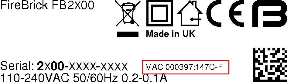
In this example, the range is specified as :-
000397:147C-F
this is interpreted as :-
- All addresses in the range start with
00:03:97:14:7 - the next digit then ranges from "C" through to "F"
- the first address in the range has zero for the remaining digits (
C:00) - the last address in the range has F for the remaining digits (
F:FF)
- the first address in the range has zero for the remaining digits (
Therefore this range spans 00:03:97:14:7C:00 to 00:03:97:14:7F:FF inclusive (1024 addresses).
If you are trying to identify an IP address allocation,
note that the exact address used within this range depends on a number of factors ; generally you should look for an IP address allocation against
any of the addresses in the range.
Alternatively, if the range specification doesn't include a hyphen, it specifies that all addresses in the range start with this 'prefix' - the first address in the range will have zero for all the remaining digits, and the last address in the range will have F for all the remaining digits. For example :-
000397:147C
is interpreted as :
- All addresses in the range start with
00:03:97:14:7C- the first address in the range has zero for the remaining digits (00)
- the last address in the range has F for the remaining digits (FF)
Therefore this range spans 00:03:97:14:7C:00 to 00:03:97:14:7C:FF inclusive (256 addresses).
If your DHCP server shows the name of the client (FB2700) that issued the DHCP request, then you will see a value that depends on whether the system name is set on the FB2700, as shown in Table C.1. Refer to Section 4.2.1 for details on setting the system name.
Table C.1. DHCP client names used
| System name | Client name used |
| not set (e.g. factory reset configuration) | FB2700 |
| set | Main application software running |
If the FB2700's system name is set, and your DHCP server shows client names, then this is likely to be the preferred way to locate the relevant DHCP allocation in a list, rather than trying to locate it by MAC address. If the FB2700 is in a factory-reset state, then the system name will not be set, and you will have to locate it by MAC address.
Table of Contents
The web interface for the FireBrick is mainly intended to be used from a web browser, however, there are a number of cases where the use from scripts or tools can be useful. This appendix covers some of the ways the FireBrick web interface can be used. Some of these are already mentioned in other sections, such as customised CQM archiving URLs, and so not repeated here. We also do not cover loading and saving a new config.
There are a great many tools for accessing web pages, in a variety of languages. Please feel free to use whichever tools you are happy with.
In this section we suggest the use of the linux command line tool curl, and all of the examples are based on this.
You will need to consider access control carefully if using scripts to access the FireBrick. In particular you need to ensure that someone that has access to the scripts, or simply a copy of the script, could not gain unfettered access to your FireBrick(s).
You will probably want to create a separate user for the script access, with a separate password. You can then make use of this with a command like curl using the --user argument in the script.
Note
We do not recommend simply hard coding the password, and it may be better to have passwords stored in a database of some sort. This will depend on your own security procedures.You could, if you have the tools to manage OTP codes, make use of an OTP seed for your script user. Remember that the authentication system allows the OTP code to be pre-pended to the password, e.g. --user name:123456password. This is recommended if using HTTP access which can be snooped upon.
We strongly recommend you have additional allow list access controls on your script user to lock down to machines which will be accessing the FireBrick. You may even want different users for different scripts, machines running scripts, and FireBricks depending on your own security policies.
It is likely that scripts, as described in this appendix, will not need to access or change the configuration on your FireBricks, and so you can lock down access for the user to restrict access to the config.
Note
If you do have scripts that update configuration, you may want to use a different user for security reasons.When using the web interface you will encounter a number of cases where there is an XML link shown. For example, in Status/Subnets. This has an XML link to /status/subnets/xml.
This is an example of one of the many places that an XML version of some user data can be accessed. We have not listed all of these in the manual as you can see them in the web pages that include the XML link.
Many of the diagnostic tools also include an XML link or check box, for example Diagnostics/Ping.
When using the web page, the page expects that you will post back a special code that was included as a hidden field. This is to prevent the use of cross site scripting where a form on a separate web page will attempt to post to your FireBrick with arguments that do something on your FireBrick, hoping you happen to be logged in to the FireBrick still on your browser.
However, where an Authentication header is used, such as the --user option on curl this requirement is dropped, and so you can make scripts work with a single curl command with authentication and arguments.
Most tools (e.g. ping) require some arguments. The simplest way to identify these is to see what is in the form on the web site.
In some cases the field names are actually taken from the command line, which means that in some cases the field name is just a number.
For example, ping needs 1 as a field with the IP address to ping, and count as the ping count. Typically all arguments are in fact optional, so do not need to be included.
The arguments need to be supplied as if sent from a form. In most cases these can be passed as a query string style, or as posted form data.
For example:-
curl http://my.firebrick.uk/diag/ping/p --user adrian:237426 --data 1=8.8.8.8 --data xml
The result being:-
<?xml version="1.0" encoding="UTF-8"?>
<status xmlns="http://firebrick.ltd.uk/xml/statusv1"
    xmlns:xsi="http://www.w3.org/2001/XMLSchema-instance"
    xsi:schemaLocation="http://firebrick.ltd.uk/xml/statusv1 http://firebrick.ltd.uk/xml/statusv1.xsd"
    firmware-version="TEST Abbotscliffe (V2.00.100 2023-10-09T14:52:22)"
    generated="2023-03-10T13:50:10Z">
<note>Pinging 8.8.8.8 from 90.155.42.98</note><ping>
<ping number='1' time='3.848' ip='8.8.8.8' note='Reply' name='google-public-dns-a.google.com'/>
<ping number='2' time='3.985' ip='8.8.8.8' note='Reply' name='google-public-dns-a.google.com'/>
<ping number='3' time='3.724' ip='8.8.8.8' note='Reply' name='google-public-dns-a.google.com'/>
<ping number='4' time='3.848' ip='8.8.8.8' note='Reply' name='google-public-dns-a.google.com'/>
<ping number='5' time='3.911' ip='8.8.8.8' note='Reply' name='google-public-dns-a.google.com'/>
<ping number='6' time='4.298' ip='8.8.8.8' note='Reply' name='google-public-dns-a.google.com'/>
<ping number='7' time='3.839' ip='8.8.8.8' note='Reply' name='google-public-dns-a.google.com'/>
<ping number='8' time='3.748' ip='8.8.8.8' note='Reply' name='google-public-dns-a.google.com'/>
<ping number='9' time='3.796' ip='8.8.8.8' note='Reply' name='google-public-dns-a.google.com'/>
<ping number='10' time='3.722' ip='8.8.8.8' note='Reply' name='google-public-dns-a.google.com'/>
<summary sent='10' received='10' loss='0.00' minimum='3.722' average='3.871' maximum='4.298'/>
</ping>
</status>
Note
The form will typically include an XML check box, hence the use of--data xml in the example so as to include this as a field that is sent in the query string.
A number of special URLs exist purely for script use. These can be accessed under
/config/ as follows :-
Table D.1. Special URLs
| URL | Type | Function |
| reboot | HTML | Simple reboot |
| reboot-when-free | HTML | Reboot when free |
| reboot-cancel | HTML | Cancel the reboot when free if possible |
| reboot-hard | HTML | Forced hard reboot now |
| capability | XML | Return XML capability |
| schema | XML | Return XML that is the internal format config edit schema |
| timestamp | Text | Timestamp of config |
| uptime | Text | Uptime |
| ip | Text | Your IP address as seen by the FireBrick |
| version | Text | Current software version |
| et | Text | Current software version, or an HTTP level error with text explaining why, such as Upgrade required. |
There are some web socket feeds available, generally these are used internally for config edit, status page, and logging, etc. However, we may add additional specific URLs for script use in due course. The general principle is that the websocket feed provides a stream of JSON objects in real time.
The status page uses /status/ but an additional port usage page /status/stats provides per second byte counts for all ports.
Note that you can define a js-url to be loaded at the end of pages to make use of these within the web user interface. This only works when logged in and from a trusted IP address, and not on pages where passwords can be entered.
An Ethernet (Layer 2) broadcast domain consists of a group of Ethernet devices that are interconnected, typically via switches, such that an Ethernet broadcast packet (which specifies a reserved broadcast address as the destination Ethernet address of the packet) sent by one of the devices is always received by all the other devices in the group. A broadcast domain defines the boundaries of a single 'Local Area Network'.
When Virtual LANs (VLANs) are not in use, a broadcast domain consist of devices (such as PCs and routers), physical cables, switches (or hubs) and possibly bridges. In this case, creating a distinct Layer 2 broadcast domain requires a distinct set of switch/hub/bridge hardware, not physically interconnected with switch/hub/bridge hardware in any other domain.
A network using Virtual LANs is capable of implementing multiple distinct Layer 2 broadcast domains with shared physical switch hardware. The switch(es) used must support VLANs, and this is now common in cost-effective commodity Ethernet switches. Inter-working of VLAN switch hardware requires that all hardware support the same VLAN standard, the dominant standard being IEEE 802.1Q.
Such switches can segregate physical switch ports into user-defined groups - with one VLAN associated with each group. Switching of traffic only occurs between the physical ports in a group, thus isolating each group from the others. Where more than one switch is used, with an 'uplink' connection between switches, VLAN tagging is used to multiplex packets from different VLANs across these single physical connections.
A IEEE 802.1Q VLAN tag is a small header prefixed to the normal Ethernet packet payload, includes a 12-bit number (range 1-4095) that identifies the tagged packet as belonging to a specific VLAN.
When a tagged packet arrives at another switch, the tag specifies which VLAN it is in, and switching to the appropriate physical port(s) occurs.
In addition to VLAN support in switches, some end devices incorporate VLAN support, allowing them to send and receive tagged packets from VLAN switch infrastructure, and use the VLAN ID to map packets to multiple logical interfaces, whilst only using a single physical interface. Such VLAN support is typically present in devices that are able to be multi-homed (have more than one IP interface), such as routers and firewalls, and general purpose network-capable operating systems such as Linux.
The FB2700 supports IEEE 802.1Q VLANs, and will accept (and send) packets with 802.1Q VLAN tags. It can therefore work with any Ethernet switch (or other) equipment that also supports 802.1Q VLANs, and therefore allows multiple logical interfaces to be implemented on a single physical port.
VLAN tagged switching is now also used in Wide-Area Layer 2 Ethernet networks, where a Layer 2 'circuit' is provided by a carrier over shared physical infrastructure. The conventional concept of a LAN occupying a small geographic area is thus no longer necessarily true.
Table of Contents
- F.1. Start-Control-Connection-Request
- F.2. Start-Control-Connection-Reply
- F.3. Start-Control-Connection-Connected
- F.4. Stop-Control-Connection-Notification
- F.5. Hello
- F.6. Incoming-Call-Request
- F.7. Incoming-Call-Reply
- F.8. Incoming-Call-Connected
- F.9. Outgoing-Call-Request
- F.10. Outgoing-Call-Reply
- F.11. Outgoing-Call-Connected
- F.12. Call-Disconnect-Notify
- F.13. WAN-Error-Notify
- F.14. Set-Link-Info
- F.15. Notes
This appendix details the L2TP protocol messages supported, and the attribute/value pairs (AVPs) which are sent and expected for each message.
Table F.1. SCCRQ
| AVP | No. | Incoming | Outgoing |
| Message Type | 0 | Value 1 | Value 1 |
| Protocol Version | 2 | Mandatory, value 1 expected | Value 1 |
| Framing Capabilities | 3 | Ignored | Value 3 |
| Bearer Capabilities | 4 | Ignored | Not sent |
| Tie Breaker | 5 | Ignored as FireBrick only accepts connections for inbound calls | Not sent |
| Firmware Revision | 6 | Ignored | FireBrick s/w version string |
| Host Name | 7 | Used to select which incoming L2TP configuration applies. | As per config/RADIUS request |
| Vendor Name | 8 | Ignored | FireBrick Ltd |
| Assigned Tunnel ID | 9 | Mandatory | Mandatory, our tunnel ID |
| Receive Window Size | 10 | Accepted, assumed 4 if not present or less than 4 is specified | Value 4 |
| Challenge | 11 | Accepted if a configured secret is defined, a response is sent in the SCCRP | Not sent at present |
Table F.2. SCCRP
| AVP | No. | Incoming | Outgoing |
| Message Type | 0 | Value 2 | Value 2 |
| Protocol Version | 2 | Value 1 expected | Value 1 |
| Framing Capabilities | 3 | Ignored | Value 3 |
| Bearer Capabilities | 4 | Ignored | Not sent |
| Firmware Revision | 6 | Ignored | FireBrick s/w ID number |
| Host Name | 7 | Logged as hostname for tunnel | Configured hostname, if defined |
| Vendor Name | 8 | Ignored | FireBrick Ltd |
| Assigned Tunnel ID | 9 | Expected as far end ID | Mandatory, our tunnel ID |
| Receive Window Size | 10 | Accepted, assumed 4 if not present or less than 4 | Not sent, assume 4 |
| Challenge | 11 | Accepted if a configured secret is defined, a response is sent in the SCCCN | Not sent at present |
| Challenge Response | 13 | Not expected at present | Sent if SCCRQ contained a challenge and we have a secret defined |
Table F.3. SCCCN
| AVP | No. | Incoming | Outgoing |
| Message Type | 0 | Value 3 | Value 3 |
| Challenge Response | 13 | Not expected | Sent if was challenged |
Table F.4. StopCCN
| AVP | No. | Incoming | Outgoing |
| Message Type | 0 | Value 4 | Value 4 |
| Result Code | 1 | Ignored (logged) | Sent as appropriate for tunnel close |
| Assigned Tunnel ID | 9 | Expected, see note | Sent if a tunnel has been allocated |
Note that a StopCCN may not have a zero tunnel ID in the header. If this is the case the source IP, port and assigned tunnel are used to identify the tunnel.
If an unknown tunnel ID is received on any any incoming packet a StopCCN is generated (once per 10 seconds) with header tunnel ID 0 and specified assigned tunnel ID.
Always responded to. Sent periodically if no other messages sent.
Table F.6. ICRQ
| AVP | No. | Incoming | Outgoing |
| Message Type | 0 | Value 10 | Value 10 |
| Assigned Session ID | 14 | Mandatory | Mandatory, our session ID |
| Call Serial Number | 15 | Accepted and passed on if relaying | Passed on incoming value |
| Bearer Type | 18 | Ignored | Not sent |
| Called Number | 21 | Accepted, used in RADIUS and passed on if relaying | Passed on incoming value |
| Calling Number | 22 | Accepted, used in RADIUS and passed on if relaying | Passed on incoming value |
| Sub-Address | 23 | Ignored | Not sent |
| Physical Channel ID | 25 | Ignored | Not sent |
Table F.7. ICRP
| AVP | No. | Incoming | Outgoing |
| Message Type | 0 | Value 11 | Value 11 |
| Assigned Session ID | 14 | Mandatory | Mandatory |
| Rx Connect Speed | 38 | Accepted | Sent when advise-speed is set. |
Note
Sending and receiving Rx Connect Speed in an ICRP message is a FireBrick specific extension. It is useful when the tunnel partner acting as the LNS is in a better position to determine the speed of the connection than the LAC.Table F.8. ICCN
| AVP | No. | Incoming | Outgoing |
| Message Type | 0 | Value 12 | Value 12 |
| Framing Type | 19 | Ignored | 1 |
| Tx Connect Speed | 24 | Accepted, used in RADIUS and passed on if relaying | Passed on incoming value |
| Initial Received LCP CONFREQ | 26 | Ignored | Not sent |
| Last Sent LCP CONFREQ | 27 | Accepted, used in RADIUS and passed on if relaying | Passed on incoming value |
| Last Received LCP CONFREQ | 28 | Accepted, used in RADIUS and passed on if relaying | Passed on incoming value |
| Proxy Authen Type | 29 | Accepted, used in RADIUS and passed on if relaying | Passed on incoming value |
| Proxy Authen Name | 30 | Accepted, used in RADIUS and passed on if relaying | Passed on incoming value |
| Proxy Authen Challenge | 31 | Accepted, used in RADIUS and passed on if relaying | Passed on incoming value |
| Proxy Authen ID | 32 | Accepted, used in RADIUS and passed on if relaying | Passed on incoming value |
| Proxy Authen Response | 33 | Accepted, used in RADIUS and passed on if relaying | Passed on incoming value |
| Private Group ID | 37 | Ignored | Not sent |
| Rx Connect Speed | 38 | Accepted, used in RADIUS and passed on if relaying | Passed on incoming value |
| Sequencing Required | 39 | Accepted on honoured | Not sent |
Not supported, ignored.
Not supported, ignored.
Not supported, ignored.
Table F.12. CDN
| AVP | No. | Incoming | Outgoing |
| Message Type | 0 | Value 14 | Value 14 |
| Result Code | 1 | Ignored (logged) | Sent as appropriate for tunnel close |
| Q.931 Cause Code | 12 | Ignored | Not sent |
| Assigned Session ID | 14 | Expected, see note | Sent if assigned |
Note that a CDN may have a zero session ID in the header. If this is the case the tunnel ID and assigned session ID are used to identify the session.
If an unknown session ID on a known tunnel ID is received on any any incoming packet a CDN is generated with header session ID 0 and specified assigned session ID.
Not supported, ignored.
Not supported, ignored.
The L2TP and PPP specifications are clear that the HDLC framing bytes are not sent or received within the L2TP packet. However, BT send type bytes (FF03) on the start of all PPP frames. This is silently discarded. Also, BT will not process packets if these type bytes are not included in outgoing packets. Sending the HDLC framing can be controlled in the config and on a per session basis using a Filter-Id in RADIUS authentication response.
BT sometimes negotiate incorrect MRUs on behalf of the LNS. Where the L2TP proxy details indicate and incorrect MRU has been negotiated then LCP negotiation is restarted and the correct MRU negotiates. This helps avoid various issues with fragmentation on some services on the internet when the broadband fully supports 1500 byte MTU. This is also relevant where the FB6000 is deliberately configured to use a smaller MRU for example when the L2TP connection is remote via a 1500 MTU link.
There are options using Filter-Id from RADIUS to force LCP restart. However this does confuse some ppp implementations as it is after authentication is complete. This can be useful where BT have provided an incorrect MRU for the end user (another bug). There is also an option to forward 1500 byte packets rather than fragmenting them. When enabled ICMP is still generated for DF and IPv6.
IP over LCP is a non standard coding of PPP packets for IPv4 and IPv6. The coding uses the LCP code (C021) instead of the IPv4 (0021) or IPv6 (0057) code. The first byte which would normally be the LCP type is 0x4X (IPv4) or 0x6X (IPv6). The FireBrick assumes any such LCP codes are IPv4/IPv6 when received, and using a RADIUS response can send IP packets using LCP. This is specifically to bypass any carrier IP specific shaping or DPI.
Table of Contents
RADIUS is used for authentication and accounting of L2TP connections. If no authentication servers are configured then authentication is not performed. If no accounting servers are configured then no accounting is generated. Multiple servers can be configured and they are processed in order. Each can have multiple IP addresses. The IP addresses are tried based on the previous performance (response time, etc). If a server does not respond a number of times as configured then it is blacklisted (see Section 15.8.1.2 for more detail).
It is possible to configure local configurations which are checked before any RADIUS authentication.
It is possible to configure L2TP so that RADIUS accounting must respond, and if not then the sessions are disconnected.
Table G.1. Access-request
| AVP | No. | Usage |
| Message-Authenticator | 80 | Message signature as per RFC2869 |
| User-Name | 1 | Username from authentication (PAP/CHAP) or proxy authentication received on L2TP |
| Called-Station-Id | 30 | Called number as received on L2TP |
| Calling-Station-Id | 31 | Calling number as received on L2TP |
| Acct-Session-Id | 44 | Unique ID for session as used on all following accounting records |
| NAS-Identifier | 32 | Configured hostname of FireBrick |
| NAS-IP-Address | 4 | NAS IPv4 address if using IPv4 |
| NAS-IPv6-Address | 95 | NAS IPv6 address if using IPv6 |
| NAS-Port | 5 | L2TP session ID |
| NAS-Port-Id | 87 | For PPPoE "port{:vlan}/MAC" |
| Service-Type | 6 | Framed |
| Framed-Protocol | 7 | PPP |
| CHAP-Password | 3 | CHAP ID and response |
| CHAP-Challenge | 60 | CHAP challenge (only present if not the same as RADIUS authenticator) |
| Framed-MTU | 12 | MTU requested by PPP, if one was requested (even if 1500) |
| Connect-Info | 77 | Text Tx speed/Rx speed from L2TP connection if known |
| Tunnel-Client-Endpoint | 66 | Indicates the L2TP tunnel configured name attribute, allowing connections via different L2TP incoming configurations to be identified |
| Proxy-State | 33 | Added to session steering RADIUS requests (i.e. previous RADIUS returned type S tunnel) |
Note that the NAS-IP-Address is normally the local end of the L2TP connection for the incoming connection. However, there is a configuration option to pass the remote end of the L2TP as the NAS-IP-Address as this is often more useful. If the remote Ip is used the NAS-Port is set to the far end L2TP session ID rather than the local end session ID. The NAS-Identified remains the name of the FB6000. This option is separately available for accounting messages.
Note that the Calling-Station-Id is included even if not present in L2TP connection if a cache platform RADIUS request matched the L2TP connection and had a Calling-Station-Id.
Table G.2. Access-Accept
| AVP | No. | Usage |
| Reply-Message | 18 | Reply message sent on PPP authentication response |
| MS-Primary-DNS-Server | 311/28 | Primary DNS address used in PPP IPCP (Vendor 311 specific) |
| MS-Secondary-DNS-Server | 311/29 | Secondary DNS address used in PPP IPCP (Vendor 311 specific) |
| DNS-Server-IPv6-Address | 169 | DNS address used in DHCPv6 (may be specified multiple times) |
| Framed-Interface-ID | 96 | Peer IPv6 Interface ID expected in PPP IPV6CP |
| Framed-IP-Address | 8 | Peer IPv4 address expected in PPP IPCP (does not support 255.255.255.255 or 255.255.255.254 yet). Maximum localpref used. |
| NAS-IP-Address | 4 | Our end IPv4 address to use in IPCP negotiation. Does not add loopback route. This is non standard. |
| Framed-Route | 22 | May appear more than once. Text format is IPv4-Address/Bits 0.0.0.0 metric. The target IP is ignored but must be valid IPv4 syntax. The metric is used as localpref in routing. |
| Delegated-IPv6-Prefix | 123 | IPv6 prefix to be routed to line. Maximum localpref used. |
| Framed-IPv6-Prefix | 97 | IPv6 prefix to be routed to line. Maximum localpref used. |
| Framed-IPv6-Route | 99 | May appear more than once. Text format is IPv6-Address/Bits :: metric. The target IP is ignored but must be valid IPv6 syntax. The metric is used as localpref in routing. Alternative format IPv6/Bits IPv4-Address metric defines that prefix is to be protocol 41 IPv4 tunneled to specified target via this link. |
| Framed-IPv6-Address | 168 | Adds a /128 IPv6 route. |
| User-Name | 1 | Username may be specified - this replaces the username already present and is then used on accounting start and relay L2TP. |
| CHAP-Challenge | 60 | Overwrite relay details: If no length then forces PAP, else forces CHAP and sets challenge. Send before CHAP-Password or User-Password in packet. |
| CHAP-Password | 3 | Overwrite relay details: This replaces the CHAP ID and CHAP response |
| User-Password | 2 | Overwrite relay details: (not, plain text, not encoded). If CHAP, sets a response based on this, else forces PAP using this password. |
| Called-Station-Id | 30 | Called number may be specified - this replaces the number already present |
| Calling-Station-Id | 31 | Calling number may be specified - this replaces the number already present |
| Chargeable-User-Identity | 89 | This is used as the preferred CQM graph name. |
| Class | 25 | Secondary CQM graph name to group sessions allowing group logging or shaping. |
| Session-Timeout | 27 | Absolute limit on session, in seconds |
| Filter-Id | 11 | See filter ID section |
| Framed-MTU | 12 | Set MTU for session |
| Connect-Info | 77 | Text tx/rx speed limit to apply to session (see below) |
| Tunnel-Type | 64 | If specified must be 3 (L2TP), L2TP is assumed. Also allows special 'R' and 'S' types, see below. |
| Tunnel-Medium-Type | 65 | If specified must be 1 (IPv4) or 2 (IPv6), syntax of endpoint is used if this is not specified |
| Tunnel-Server-Endpoint | 67 | Text IPv4 or IPv6 address of endpoint (FQDN is not accepted) |
| Tunnel-Client-Auth-ID | 90 | Hostname to quote on outgoing tunnel, if omitted then configured FireBrick hostname is used |
| Tunnel-Password | 69 | Shared secret to use on outgoing tunnel (encrypted), if omitted then assumed no secret |
| Tunnel-Assignment-ID | 81 | Name of outgoing tunnel shaper/graph. Also groups sessions together in a tunnel as per RFC. Only use valid text graph names. |
| Tunnel-Preference | 83 | Specifies preference order when multiple tagged endpoints sent |
Note that whilst a RADIUS response is normally relatively small it can get larger when multiple tunnel endpoints are included. Fragmented responses are handled but there is an internal limit to the size of response that can be processed - as such we recommend keeping the response to a single un-fragmented packet of up to 1500 bytes. You can use tag 0 for common settings such as Tunnel-Client-Auth-ID or Tunnel-Password when using multiple endpoints in order to reduce the size of the response.
The Tunnel-Type can be special, non-RFC values: 'R' (0x52)or 'S' (0x53) to indicate that the Tunnel-Server-EndPoint is the name or IP of a further RADIUS server to be interrorgated. For 'R' this may respond with any valid authentication response. For 'S' the response will have all IP assignments filtered, and also not allow a Tunnel-Type 'S' response. Only one, tag 0 (untagged), RADIUS referral response will be accepted. The endpoint specified is server name or IP, and can have a number of numeric values appended (#port, >mintimeout, <maxtimeout, *scale, ?maxqueue).
The Connect-Info response can be a simple number (bits/second) tx rate, or a number followed by a % where this sets a speed based on a percentage of connection line speed. This can be followed by a slash (/) and the same for rx rate if required (default is rx is not limited). It is also possible to set long term shapers, this involves a number of additional parameters in the string prefixed with characters: > min, < max, _ minburst, and \ step. You need to include the Chargeable-User-Identity in the request for speeds to be set.
Some of the response fields are somewhat unconventional, such as User-Name and User-Password, allowing existing entries to be overwritten. These impact any details passed in a RADIUS accounting start and also impact relayed L2TP connections. Note that these can also impact if a secondary RADIUS request is done (e.g. if far end sends a new CHAP response, for example).
The RADIUS authentication response can include Delegated-IPv6-Prefix, Framed-IPv6-Prefix, and Framed-IPv6-Route in order to route native IPv6 prefixes to the line. If there are any native IPv6 routes, or the Framed-IPv6-Interface attribute was specified, then IPV6CP negotiation is started. Framed-IPv6-Route can also be used to added IPv4 tunneled routes to the line. The FE80::/10 link local address negotiated with IPV6CP is not added to the routing for the line.
The client can send a Router solicitation to which the FireBrick will reply advising to use DHCPv6 for addressing. Once a router solicitation is sent, periodic Router Advertisements will then be sent on the connection by the Firebrick.
The client can use DHCPv6 to request an IA_NA (/128 link address), IA_TA (/128 temp link address), IA_PD (Prefix Delegation) and DNS servers. Prefixes are delegated based on the order in the DHCPv6 request and the order of Delegated-IPv6-Prefix, Framed-IPv6-Prefix, and then Framed-IPv6-Route, with multiple such entries in the order that they appeared in the RADIUS response. Such prefixes are not split up if a smaller prefix is requested, but the first part of a prefix is delegated.
As you can see, it is possible to send back CHAP-Challenge and CHAP-Password or User-Password to override those received by proxy or negotiation. This is mainly used when relaying the L2TP onwards and changes the proxy authentication field sent. This also overrides the Last LCP Tx proxy setting to show PAP/CHAP or no authentication as having been negotiated.
Note that an authentication reject will normally cause the reply message to be sent as an authentication reject message. The reply "Try another" causes the L2TP session to be closed with result/error 2/7 (Try another) without sending an authentication reply on PPP.
Table G.4. Accounting-Start
| AVP | No. | Usage |
| Acct-Status-Type | 40 | 1 Start |
| User-Name | 1 | Username from authentication (PAP/CHAP) or proxy authentication received on L2TP or received in authentication response |
| Class | 25 | From authentication response if present |
| Chargeable-User-Identity | 89 | Graph name that applies, sanitised to comply with CQM graph name rules.. |
| Called-Station-Id | 30 | Called number as received on L2TP |
| Calling-Station-Id | 31 | Calling number as received on L2TP |
| Service-Type | 6 | Framed |
| Framed-Protocol | 7 | PPP |
| Framed-MTU | 12 | Final MTU being used for session |
| Filter-Id | 11 | Filters in use |
| Session-Timeout | 27 | Absolute limit on session, in seconds, if specified in authentication reply |
| Framed-Interface-ID | 96 | Peer IPv6 Interface ID from PPP IPV6CP |
| Framed-IP-Address | 8 | Peer IPv4 address negotiated in PPP (normally from authentication response) |
| Connect-Info | 77 | Text Tx speed/Rx speed in use |
| Acct-Delay-Time | 41 | Seconds since session started |
| Acct-Event-Timestamp | 55 | Session start time (unix timestamp) |
| Acct-Session-Id | 44 | Unique ID for session |
| NAS-Identifier | 32 | Configured hostname of FireBrick |
| NAS-IP-Address | 4 | NAS IPv4 address if using IPv4 |
| NAS-IPv6-Address | 95 | NAS IPv6 address if using IPv6 |
| NAS-Port | 5 | L2TP session ID |
| Tunnel-Type | 64 | Present for relayed L2TP sessions, L2TP |
| Tunnel-Medium-Type | 65 | Present for relayed L2TP, 1 (IPv4) or 2 (IPv6) |
| Tunnel-Client-Endpoint | 66 | Present for relayed L2TP, text IPv4 or IPv6 address of our address on the outbound tunnel |
| Tunnel-Server-Endpoint | 67 | Present for relayed L2TP, text IPv4 or IPv6 address of the far end address of the outbound tunnel |
| Tunnel-Assignment-ID | 82 | Present for relayed L2TP, text local L2TP tunnel ID |
| Tunnel-Client-Auth-ID | 90 | Present for relayed L2TP, local end hostname quoted by outgoing tunnel |
| Tunnel-Server-Auth-ID | 91 | Present for relayed L2TP, far end hostname quoted by outgoing tunnel |
Note that most parameters are not included in interim and stop accounting records. The acct-session-id should be used by accounting servers to correlate interim and stop records with the start record. The graph name could be used, but is only available where there is a graph. If too many different graphs then that is not present. Some exceptions apply as they can be changed by a change of authorisation RADIUS request, such as Connect-Info.
Table G.5. Accounting-Interim
| AVP | No. | Usage |
| Acct-Status-Type | 40 | 3 Interim-Update |
| Acct-Delay-Time | 41 | Seconds since accounting data collected |
| Acct-Event-Timestamp | 55 | Data collected time (unix timestamp) |
| Acct-Session-Id | 44 | Unique ID for session |
| Chargeable-User-Identity | 89 | Graph name that applies, sanitised to comply with CQM graph name rules.. |
| Connect-Info | 77 | Text Tx speed/Rx speed in use |
| Framed-IP-Address | 8 | Peer IPv4 address negotiated in PPP (normally from authentication response) |
| NAS-Identifier | 32 | Configured hostname of FireBrick |
| NAS-IP-Address | 4 | NAS IPv4 address if using IPv4 |
| NAS-IPv6-Address | 95 | NAS IPv6 address if using IPv6 |
| NAS-Port | 5 | L2TP session ID |
| Acct-Input-Octets | 42 | Rx byte count |
| Acct-Input-Gigawords | 52 | Rx byte count (high 4 bytes) |
| Acct-Output-Octets | 43 | Tx byte count |
| Acct-Output-Gigawords | 53 | Tx byte count (high 4 bytes) |
| Acct-Input-Packets | 47 | Rx packet count |
| Acct-Output-Packets | 48 | Tx packet count |
| Tunnel-Type | 64 | Present for relayed L2TP sessions, L2TP |
| Tunnel-Medium-Type | 65 | Present for relayed L2TP, 1 (IPv4) or 2 (IPv6) |
| Tunnel-Client-Endpoint | 66 | Present for relayed L2TP, text IPv4 or IPv6 address of our address on the outbound tunnel |
| Tunnel-Server-Endpoint | 67 | Present for relayed L2TP, text IPv4 or IPv6 address of the far end address of the outbound tunnel |
| Tunnel-Assignment-ID | 82 | Present for relayed L2TP, text local L2TP tunnel ID |
| Tunnel-Client-Auth-ID | 90 | Present for relayed L2TP, local end hostname quoted by outgoing tunnel |
| Tunnel-Server-Auth-ID | 91 | Present for relayed L2TP, far end hostname quoted by outgoing tunnel |
As accounting interim update plus
Cause codes of note are 2(Lost-Carrier) which is sent if LCP echos do not reply for several seconds, and 14(Port-Suspended) which is sent if the dos-limit is exceeded on a session. For DOS handling is is recommended that subsequent authentication requests are rejected for several minutes or a fake accept is and session-timeout is used as DOS attacks usually continue until the customer is off-line.
A disconnect message is accepted as per RFC5176, if the session can be disconnected, and ACK is sent, else a NAK
Table G.7. Disconnect
| AVP | No. | Usage |
| Acct-Session-Id | 44 | Unique ID for session |
| Chargeable-User-Identity | 89 | This is used as CQM graph name. |
| Acct-Terminate-Cause | 49 | Cause code as appropriate to be used in accounting stop message |
The session is identified by Acct-Session-Id if present, else by Chargeable-User-Identity. No other identification parameters are supported. If sent then they are ignored.
A change of authorisation message is accepted as per RFC5176
Table G.8. Change-of-Authorisation
| AVP | No. | Usage |
| Acct-Session-Id | 44 | Unique ID for session |
| Chargeable-User-Identity | 89 | This is used as CQM graph name. |
| Framed-Route | 22 | May appear more than once. Text format is IPv4-Address/Bits 0.0.0.0 metric. The target IP is ignored but must be valid IPv4 syntax. The metric is used as localpref in routing. |
| Delegated-IPv6-Prefix | 123 | IPv6 prefix to be routed to line. Maximum localpref used. |
| Framed-IPv6-Prefix | 97 | IPv6 prefix to be routed to line. Maximum locapref used. |
| Framed-IPv6-Route | 99 | May appear more than once. Text format is IPv6-Address/Bits :: metric. The target IP is ignored but must be valid IPv6 syntax. The metric is used as localpref in routing. Alternative format IPv6/Bits IPv4-Address metric defines that prefix is to be protocol 41 IPv4 tunneled to specified target via this link. |
| Session-Timeout | 27 | Absolute limit on session, in seconds |
| Terminate-Action | 29 | If not specified, or 0, then terminate on Session-Timeout or Quota reached, else send RADIUS Interim accounting update (not an Access Request) |
| Connect-Info | 77 | Text tx speed limit to apply to session (see below) |
| Filter-Id | 11 | See filter ID section |
The session is identified by Acct-Session-Id if present, else by Chargeable-User-Identity. No other identification parameters are supported. If sent then they are ignored.
Parameters are left unchanged if not specified.
- If any route entries (IPv4 or IPv6) are present then the existing routing (apart from the PPP endpoint address) are all removed and replaced with what has been sent. To clear all routes send a framed route with a blank string. The Framed-IP-Address cannot be changed.
- To clear the session timeout send a value of 0.
- To clear remove shaping send a Connect-Info of "0".
No other parameters are supported, and if sent then they are ignored
The Connect-Info response can be a simple number (bits/second) tx rate, or a number followed by a % where this sets a speed based on a percentage of current line speed. It is also possible to set long term shapers where a Chargeable-User-Identity is also included, this involves a number of additional parameters in the string prefixed with characters: > min, < max, _ minburst, and \ step.
The Filter-ID can be set in authentication response and change of authorisation. There can be many records. Each can have many filters. Each filter is of the form of a letter possibly followed by number digits. The accounting start lists relevant filters that have been set, each in a separate filter-id AVP. Unknown filters are ignored.
Table G.9. Filter-ID
| Filter | meaning |
| Tn | Set routing table for payload traffic. This can be used for private routing, and for walled garden / credit control |
| An | Specify this connection is a member of a closed user group n (1-32767) but has normal IP access as well. This connection is not filtered by traffic can go to/from connections that are filtered in the same CUG |
| Rn | Specify this connection is a member of a closed user group n (1-32767) and is restricted to sending traffic to/from connections in the same CUG. |
| H | Sets the connection to send HDLC framing headers on all PPP packets. This adds 2 extra byte to the packet. This is the default setting. |
| h | Sets the connection not to send HDLC framing headers on all PPP packets. This is in accordance with the L2TP/PPP RFCs. This does not work on BT 21CN BRASs. |
| F | Sets TCP MTU fix flag which causes the MTU option in TCP SYN to be adjusted if necessary to fit MTU. |
| f | Sets no TCP MTU fix |
| M | Sets the connection to ignore the MRU. Actually, the MRU is used to generate ICMP errors for IPv6 and IPv4 with DF set, but otherwise full size packets are sent on the connection even if a lower MRU was advised. This is in accordance with the PPP RFC but breaks some routers that do not accept 1500 byte packets (e.g. PPPoE) |
| m | Sets the connection to fragment IPv4 packets with DF not set that are too big for the advised MRU. This is the default |
| L | This is not a filter and not confirmed back on accounting start and not valid on Change of Authorisation. It forces a restart of LCP negotiation. This is useful when BRASs lie about negotiated LCP (such as BTs 21CN BRASs) |
| l | This is not a filter and not confirmed back on accounting start and not valid on Change of Authorisation. It stops an LCP negotiation restart that may be planned, e.g. due to an MRU mismatch. |
| X | Pad packets to 74 bytes if length fields appears to be less - needed to work around bug in BT 20CN BRAS for IPv6 in IP over LCP mode |
| C | Send all IPv4 and IPv6 using the LCP type code (only works if FireBrick doing PPP at far end) |
| I | Mark session isolated from other L2TP sessions (no direct packets from other L2TP sessions allowed) |
| J | Mark session for latency adjust on bonding (adds half round trip latency to bonding calculations) |
| O | Mark session as low-priority (see shaper and damping) |
| P | Mark session as premium (see shaper and damping) |
| D | Mark session as blackhole (Normal IPv4/IPv6 routes are announced as black hole routes, and any BGP is not restricted to local-as, etc. Does not apply to 6over4 routes) |
| d | Mark session as not blackhole |
| b | Disable anti-spoofing source filtering |
| Sn | Set LCP echo rate to n seconds (default 1) |
| sn | Set LCP timeout rate to n seconds (default 10) |
| q[+]n | Specify [or add to] quota for tx bytes. Use either q or Q. Action depends on Terminate-Action. |
| Q[+]n | Specify [or add to] quota for total (tx+rx) bytes. |
For change of authorisation the absence of a filter has no effect. To set normal routing table 0 zero, send T0. To set not a member of a CUG send A0.
L2TP relay means that an incoming call (ICRQ) is relayed to another L2TP endpoint. The decision of which calls to relay to what endpoint can be made in one of two ways:-
- Configured pattern match based on calling number, called number, or login.
- RADIUS response to initial authentication request advising new endpoint for connection.
A test is made against the config on the initial connection based on known data. This is calling number (if present), called number (if present) and login (proxy_auth_name if present). If a match is found the call is relayed with no additional PPP packets exchanged.
If there is no proxy LCP provided, or the provided negotiation conflicts with the configuration, then LCP negotiation is completed.
If there is no proxy authentication, PPP authentication is start until a response/login is received from the peer (assuming authentication is required in the config).
At this point a further check is made for a configured relay which can now be based on a login if one was not present before.
RADIUS authentication is completed, and if the response indicates a relay then the call is relayed.
The relayed call includes the incoming call parameters, and any LCP and authentication parameters that may have been negotiated at that point.
The Filter ID T which would normally set the payload table when terminating traffic is instead used to set the routing table for the outgoing relay tunnel.
Each session gets a CQM graph which uses one second LCP requests and produces detailed loss/latency graphs for the session. The graph name is picked based on the first available of :-
- Chargeable-User-Identity sent in the RADIUS authentication response.
- Calling-Station-Id from L2TP.
- User-name in RADIUS athentication response.
- Proxy-Auth-Name from L2TP.
- Negotiated user name from PAP/CHAP.
If a second session starts with the same graph name as an existing session then the existing session is cleared with cause 13(Preempted). It is recommended that a unique circuit ID is passed as the Chargeable-User-Identity in the authentication response to allow simple location of graphs.
Normally the FireBrick sends regular LCP echos and generates a loss/latency graph. Where this is not enabled (LCP Rate 0 or no graph set at all) then graphs are created but with no loss/latency. On a relayed L2TP connection the LCP echos are normally generated by the far ends and passed through by the FireBrick. However, if a RADIUS reply sets the LCP rate/timeout and provides tunnel relay, then the incoming side of the relayed connection will use LCP echos from the FireBrick in the middle of the connection and not pass these through - this means on the o/g connection the FireBrick answers LCP echos from the relayed LNS.
IP over LCP is a non standard coding of PPP packets for IPv4 and IPv6. The coding uses the LCP code (C021) instead of the IPv4 (0021) or IPv6 (0057) code. The first byte which would normally be the LCP type is 0x4X (IPv4) or 0x6X (IPv6). The FireBrick assumes any such LCP codes are IPv4/IPv6 when received, and using a RADIUS response can send IP packets using LCP. This is specifically to bypass any carrier IP specific shaping or DPI.
Each session can have a CUG defined (1-32768) which may be allow or restrict. Interfaces (port/VLAN) may also be defined in the same way. A packet from an interface/session with a CUG is tagged with that packet. If the source is restricted that packet can only leave via an interface/session with the same CUG. Similarly if the target interface/session is restricted than only a packet tagged with the same CUG can be sent to it.
The FireBrick operates independent routing cores allowing a totally independent routing table to be used for L2TP wrapper traffic and payload traffic. It is also possible to set the payload table in use on a per session basis from RADIUS thus allowing a walled garden to be set up, or a private network, or simple an unusable session.
Table of Contents
RADIUS is used to authenticate REGISTRATION requests allowing registration of telephones. It is also used to authenticate INVITE requests and provide call routing information.
RADIUS Accounting is used to provide details of calls in progress.
Authentication requests are used for SIP requests where the request is to be challenged, e.g. REGISTER, INVITE, REFER, SUBSCRIBE, OPTIONS, etc.
The format mostly follows RFC5090. There is an option (radius-challenge) to send the RADIUS authentication request before receiving authentication data from the requestor, which allows progress without authentication credentials, but more likely to be used to send a ACCESS_CHALLENGE response to customise the challenge sent to the requestor.
Table H.1. Access-request
| AVP | No. | Usage |
| User-Name | 1 | Name of locally configured telephone user, or @ and locally configured carrier name |
| Chargeable-User-Identity | 89 | If request relates to locally configured telephone user or carrier |
| Message-Authenticator | 80 | Message signature as per RFC2869 |
| Called-Station-Id | 30 | Local part of To: header |
| Calling-Station-Id | 31 | Local part of From: header |
| NAS-Identifier | 32 | Configured hostname of FireBrick |
| NAS-IP-Address | 4 | Requestor IPv4 address if using IPv4 |
| NAS-IPv6-Address | 95 | Requestor IPv6 address if using IPv6 |
| NAS-Port | 5 | Requestor UDP port |
| NAS-Port-Type | 61 | Send with value 5 (virtual) if NAT detected |
| Class | 25 | User Agent string |
| Acct-Multi-Session-Id | 50 | Call-ID from request |
| Digest-Response | 103 | Digest Response |
| Digest-Realm | 104 | Digest Realm |
| Digest-Nonce | 105 | Digest Nonce |
| Digest-Method | 108 | Digest Method |
| Digest-URI | 109 | Digest URI, or URI from request if no Authorization digest present |
| Digest-QOP | 110 | Digest QOP |
| Digest-Algorithm | 111 | Digest Algorithm |
| Digest-CNonce | 113 | Digest CNonce |
| Digest-Nonce-Count | 114 | Digest Nonce Count (NC) |
| Digest-Username | 115 | Digest Username |
| Digest-Opaque | 116 | Digest Opaque |
| SIP-AOR | 121 | Contact URI |
| Session-Timeout | 27 | Time from Expires header |
| Acct-Terminate-Cause | 49 | Only sent for a redirect call routing, the redirect code, e.g. 301/302 |
Table H.2. Access-Challenge
A challenge response allows the authentication details to be specified. By default this is not required as the FB2700 will generate a challenge.
| AVP | No. | Usage |
| Digest-Realm | 104 | Digest Realm |
| Digest-Nonce | 105 | Digest Nonce |
| Digest-QOP | 110 | Digest QOP |
| Digest-Algorithm | 111 | Digest Algorithm |
| Digest-Opaque | 116 | Digest Opaque |
| Digest-Stale | 120 | Digest Stale |
Table H.3. Access-Accept
| AVP | No. | Usage |
| Calling-Station-Id | 31 | Calling number to be set up for tel:number routing to this registration, if omitted then the registration is not recorded |
| Session-Timeout | 27 | Time to send in reply Expires header |
| SIP-AOR | 121 | SIP URI Contact for 302 redirect response. |
Note that this section is not yet complete
Table H.4. Access-Accept
| AVP | No. | Usage |
| Chargeable-User-Identity | 89 | Identity to be used on accounting records |
| Called-Station-Id | 30 | Overrides Dialled number of this call. |
| Calling-Station-Id | 31 | Overrides CLI to use on this call, Anonymous will flag as withheld CLI, Allowed to force allow CLI, and username@hostname for new from address. |
| User-Name | 1 | Replaces the Name of the this call. |
| Filter-Id | 11 | Adds a call recording email address to this call. |
| SIP-AOR | 121 | Creates a new outgoing call leg. |
| Callback-Number | 19 | Set P-Asserted-Id number, all legs of outgoing call |
See Section 18.12.2.1 for details of call routing.
Table H.6. Accounting-Start
| AVP | No. | Usage |
| User-Name | 1 | SIP URI for our end of the call leg |
| Callback-ID | 20 | SIP URI for other end of the call leg |
| Called-Station-Id | 30 | Dialled number as received |
| Calling-Station-Id | 31 | Calling number as received |
| Acct-Status-Type | 40 | 1 Start |
| Acct-Session-Id | 44 | Unique ID for call leg |
| Acct-Multi-Session-Id | 50 | SIP Call ID for call leg |
| Acct-Event-Timestamp | 55 | Time call started trying |
| NAS-Identifier | 32 | Configured hostname of FireBrick |
| NAS-IP-Address | 4 | Far end IPv4 address for SIP if using IPv4 |
| NAS-IPv6-Address | 95 | Far end IPv6 address for SIP if using IPv6 |
| NAS-Port | 5 | Far end UDP port for SIP |
Table H.7. Accounting-Interim
| AVP | No. | Usage |
| User-Name | 1 | SIP URI for our end of the call leg |
| Callback-ID | 20 | SIP URI for other end of the call leg |
| Called-Station-Id | 30 | Dialled number as received |
| Calling-Station-Id | 31 | Calling number as received |
| Acct-Status-Type | 40 | 3 Interim |
| Acct-Session-Id | 44 | Unique ID for session |
| Acct-Multi-Session-Id | 50 | SIP Call ID for call leg, and second instance is Session-Id of linked call |
| Acct-Event-Timestamp | 55 | Time call answered |
| NAS-Identifier | 32 | Configured hostname of FireBrick |
| NAS-IP-Address | 4 | Far end IPv4 address for SIP if using IPv4 |
| NAS-IPv6-Address | 95 | Far end IPv6 address for SIP if using IPv6 |
| NAS-Port | 5 | Far end UDP port for SIP |
Note
If the call is connected to another call leg then a second Acct-Session-Id is included with details of the linked call leg.As accounting interim update plus
Table H.8. Accounting-Stop
| AVP | No. | Usage |
| User-Name | 1 | SIP URI for our end of the call leg |
| Callback-ID | 20 | SIP URI for other end of the call leg |
| Called-Station-Id | 30 | Dialled number as received |
| Calling-Station-Id | 31 | Calling number as received |
| Acct-Status-Type | 40 | 2 Stop |
| Acct-Session-Id | 44 | Unique ID for session |
| Acct-Multi-Session-Id | 50 | SIP Call ID for call leg |
| Acct-Terminate-Cause | 49 | Cause code as appropriate |
| Acct-Event-Timestamp | 55 | Time call ended |
| Chargeable-User-Identity | 89 | CUI for this call |
| NAS-Identifier | 32 | Configured hostname of FireBrick |
| NAS-IP-Address | 4 | Far end IPv4 address for SIP if using IPv4 |
| NAS-IPv6-Address | 95 | Far end IPv6 address for SIP if using IPv6 |
| NAS-Port | 5 | Far end UDP port for SIP |
Table of Contents
- I.1. Conventions
- I.2. Firebrick-specific structures for BGP
- I.3. Firebrick-specific structures for IPSec
- I.4. Firebrick-specific structures for L2TP
- I.5. Firebrick-specific structures for VoIP/SIP
- I.6. Firebrick CPU usage
- I.7. Firebrick system stats
- I.8. Monitoring for general system features
- I.9. System wide status
This appendix details the SNMP objects that are specific to the FireBrick.
To avoid writing out very repetitive (and long) OIDs this appendix uses a substitution notation when describing structures.
The OIDs contain the names of indices and an X representing the structure field number given by the matching column in the following table.
So if the OID given in the manual is iso.1.2.3.4.X.anIndex then the OID for the first item described in the table row with column X = 3 would be: iso.1.2.3.4.3.1
In some structures IP addresses may be used as indices into SNMP tables. When this is the case the IP must be encoded into the OID for the resource. This encoding consists of the following separated by dots:
- The IP type:
1for IPv4,2for IPv6. - A length prefixed array of the bytes of the address in network order.
Example I.1.
10.0.1.12 the IP type is 1 and the length is 4.
Therefore the OID fragment 1.4.10.0.1.12 could be used as an index.
Example I.2.
2001::32 the IP type is 2 and the length is 16.
Therefore the OID fragment 2.16.32.1.0.0.0.0.0.0.0.0.0.0.0.0.0.50 could be used as an index.
OID: iso.3.6.1.4.1.24693.100.179.1.1.X.fbBgpPeerAddressType.fbBgpPeerAddress
Table I.1. Indices
| Name | Type | Meaning |
| fbBgpPeerAddressType | InetAddressType | The address type of fbBgpPeerAddressAddr. |
| fbBgpPeerAddress | InetAddress (with length prefix, see Section I.1.1) | The internet address for the peer. The type of the address is determined by the value of the fbBgpPeerAddressType object. |
Table I.2. Fields
| X | MIB name | Type | Meaning |
| 1 | fbBgpPeerAddressType | InetAddressType | The address type of fbBgpPeerAddressAddr. |
| 2 | fbBgpPeerAddress | InetAddress | The internet address for the peer. The type of the address is determined by the value of the fbBgpPeerAddressType object. |
| 3 | fbBgpPeerName | DisplayString | The name of the BGP Peer |
| 4 | fbBgpPeerState | FbBgpPeerState (Table I.3) | The current state of the BGP Peer |
| 5 | fbBgpPeerRemoteAS | Integer32 | The remote AS of the BGP Peer |
| 6 | fbBgpPeerReceivedIpv4Prefixes | Integer32 | The number of IPv4 prefixes received from the BGP Peer |
| 7 | fbBgpPeerSecondsSinceLastChange | Integer32 | The number of seconds since the last state change for the BGP Peer |
| 8 | fbBgpPeerReceivedIpv6Prefixes | Integer32 | The number of IPv6 prefixes received from the BGP Peer |
| 9 | fbBgpPeerExported | Integer32 | The number of prefixes exported to the BGP Peer |
| 10 | fbBgpPeerLocalAddressType | InetAddressType | The address type of fbBgpPeerLocalAddress. |
| 11 | fbBgpPeerLocalAddress | InetAddress | The local internet address used for this peer. The type of the address is determined by the value of the fbBgpPeerAddressType object. |
| 12 | fbBgpPeerLocalAS | Integer32 | The local AS number for the BGP Peer |
| 13 | fbBgpPeerTableId | Integer32 | The routing table number for this BGP Peer. |
| 14 | fbBgpPeerMaxPrefixes | Integer32 | Max prefixes accepted from this peer. |
| 15 | fbBgpPeerMaxPrefixesHit | TruthValue | Prefix limit was hit, so prefixes from this peer have been dropped. |
Table I.3. FbBgpPeerState - The state of a BGP peer
| Value | Meaning |
| 0 | Disabled or in error backoff state or inbound only peer |
| 1 | Attempting to connect |
| 2 | Awaiting open message (incoming) |
| 3 | Awaiting response to open, or for TCP to establish (outgoing) |
| 4 | Awaiting confirmation of establishment |
| 5 | Connection established |
| 6 | Closing or awaiting cleanup |
| 7 | Withdrawing everything and waiting for propagation |
| 8 | Shutdown |
OID: iso.3.6.1.4.1.24693.100.500.1.X
Table I.4. Fields
| X | MIB name | Type | Meaning |
| 1 | fbIPsecEstablished | Integer32 | The count of currently established IKE connections. |
| 2 | fbIPsecHalfOpen | Integer32 | The count of incoming IKE connections which have not yet authorized. |
OID: iso.3.6.1.4.1.24693.100.500.2.1.X.fbIPsecConnectionIndex
Table I.6. Fields
| X | MIB name | Type | Meaning |
| 2 | fbIPsecConnectionName | DisplayString | The config name for this connection |
| 3 | fbIPsecConnectionState | FbIPsecConState (Table I.7) | The current state for this connection |
| 4 | fbIPsecConnectionUptime | TimeTicks | The uptime for this connection |
| 5 | fbIPsecConnectionLocalID | DisplayString | The local IKE ID for this connection |
| 6 | fbIPsecConnectionPeerID | DisplayString | The peer IKE ID for this connection |
| 7 | fbIPsecConnectionPeerAddress | DisplayString | The peer's IP address for this connection |
Table I.7. FbIPsecConState - The state of an IPsec connection
| Value | Meaning |
| 0 | Bad config (item ignored) |
| 1 | disabled by profile |
| 2 | Not up (waiting for peer to initiate) |
| 3 | Not up (on-demand connection) |
| 4 | Lingering (old connection waiting to be cleared) |
| 5 | Waiting to reconnect after failure |
| 6 | Down |
| 7 | Initiating - processing EAP |
| 8 | Initiating - processing authorization |
| 9 | Initiating - initial negotiation |
| 10 | Closing |
| 11 | Childless - IKE connection established but no data channel present |
| 12 | Connected |
OID: iso.3.6.1.4.1.24693.100.1701.0.1.X
Table I.8. Fields
| X | MIB name | Type | Meaning |
| 0 | fbL2tpFreeTunnels | Integer32 | Number of tunnels in FREE state |
| 1 | fbL2tpOpeningTunnels | Integer32 | Number of tunnels in OPENING state |
| 2 | fbL2tpLiveIncomingTunnels | Integer32 | Number of tunnels in LIVE (Incoming) state |
| 3 | fbL2tpLiveOutgoingTunnels | Integer32 | Number of tunnels in LIVE (Outgoing) state |
| 4 | fbL2tpClosingTunnels | Integer32 | Number of tunnels in CLOSING state |
| 5 | fbL2tpFailedTunnels | Integer32 | Number of tunnels in FAILED state |
| 6 | fbL2tpClosedTunnels | Integer32 | Number of tunnels in CLOSED state |
OID: iso.3.6.1.4.1.24693.100.1701.0.2.X
Table I.9. Fields
| X | MIB name | Type | Meaning |
| 0 | fbL2tpFreeSessions | Integer32 | Number of sessions in FREE state |
| 1 | fbL2tpWaitingSessions | Integer32 | Number of sessions in WAITING state |
| 2 | fbL2tpOpeningSessions | Integer32 | Number of sessions in OPENING state |
| 3 | fbL2tpNegotiatingSessions | Integer32 | Number of sessions in NEGOTIATING state |
| 4 | fbL2tpAuthPendingSessions | Integer32 | Number of sessions in AUTH-PENDING state |
| 5 | fbL2tpStartedSessions | Integer32 | Number of sessions in STARTED state |
| 6 | fbL2tpLiveSessions | Integer32 | Number of sessions in LIVE state |
| 7 | fbL2tpAcctPendingSessions | Integer32 | Number of sessions in ACCT-PENDING state |
| 8 | fbL2tpClosingSessions | Integer32 | Number of sessions in CLOSING state |
| 9 | fbL2tpClosedSessions | Integer32 | Number of sessions in CLOSED state |
| 10 | fbL2tpSessionNegotiationSlotsFree | Integer32 | Number of session negotiation slots free |
OID: iso.3.6.1.4.1.24693.100.1701.1.1.X.fbL2tpPeerAddressType.fbL2tpPeerAddress
Table I.10. Indices
| Name | Type | Meaning |
| fbL2tpPeerAddressType | InetAddressType | The internet address type for the peer. |
| fbL2tpPeerAddress | InetAddress (with length prefix, see Section I.1.1) | The internet address for the peer. The type of the address is determined by the value of the fbL2tpAddressType object. |
Table I.11. Fields
| X | MIB name | Type | Meaning |
| 1 | fbL2tpPeerAddressType | InetAddressType | The internet address type for the peer. |
| 2 | fbL2tpPeerAddress | InetAddress | The internet address for the peer. The type of the address is determined by the value of the fbL2tpAddressType object. |
| 3 | fbL2tpPeerLoginName | DisplayString | The login name of the L2TP Peer |
| 4 | fbL2tpPeerHostName | DisplayString | The host name of the L2TP Peer |
| 5 | fbL2tpPeerInTunnels | Integer32 | The number of inbound tunnels from the L2TP peer |
| 6 | fbL2tpPeerOutTunnels | Integer32 | The number of outbound tunnels from the L2TP peer |
| 7 | fbL2tpPeerOldestUptime | Integer32 | The uptime of the oldest tunnel from the L2TP peer |
| 8 | fbL2tpPeerLiveTunnels | Integer32 | The number of live tunnels from the L2TP peer |
| 9 | fbL2tpPeerSessions | Integer32 | The number of sessions from the L2TP peer |
| 10 | fbL2tpPeerGraphName | DisplayString | The graph name of the L2TP peer |
OID: iso.3.6.1.4.1.24693.100.5060.X
Table I.12. Fields
| X | MIB name | Type | Meaning |
| 1 | fbSipActiveLegs | Integer32 | The total number of active call legs on this Firebrick |
| 2 | fbSipRadiusRegs | Integer32 | The number of RADIUS-based incoming registrations on this Firebrick |
| 5 | fbSipMixerUsage | Integer32 | The number of mixers in use on this Firebrick |
| 6 | fbSipMixerHWM | Integer32 | The maximum number of mixers simultaneously used at any time on this Firebrick |
| 7 | fbSipCarriers | Integer32 | The number of carriers on this Firebrick |
| 8 | fbSipMixerMax | Integer32 | The maximum number of mixers it is possible to have on this Firebrick |
OID: iso.3.6.1.4.1.24693.100.5060.3.1.X.fbSipCarrierIndex
Table I.13. Indices
| Name | Type | Meaning |
| fbSipCarrierIndex | Integer32 | The index of the SIP carrier in the carriers table |
Table I.14. Fields
| X | MIB name | Type | Meaning |
| 1 | fbSipCarrierName | DisplayString | The config name of this carrier |
| 2 | fbSipCarrierTotalLegs | Integer32 | The total number of call legs for this carrier |
| 3 | fbSipCarrierConnectedLegs | Integer32 | The number of connected call legs for this carrier |
OID: iso.3.6.1.4.1.24693.100.5060.4.1.X.fbSipPhoneIndex
Table I.15. Indices
| Name | Type | Meaning |
| fbSipPhoneIndex | Integer32 | The index of the phone in the telephone table |
Table I.16. Fields
| X | MIB name | Type | Meaning |
| 1 | fbSipPhoneName | DisplayString | The name of this telephone |
| 2 | fbSipPhoneTotalLegs | Integer32 | The total number of call legs for this telephone |
| 3 | fbSipPhoneConnectedLegs | Integer32 | The number of connected call legs for this telephone |
OID: iso.3.6.1.4.1.24693.100.2.1.1.X.fbCpuPeriod.fbCpuCore
Table I.17. Indices
| Name | Type | Meaning |
| fbCpuPeriod | Integer32 | The period in minutes covered by this table entry. Zero indicates that an instantaneous value is required. Max is 30 minutes. |
| fbCpuCore | Integer32 | The CPU core number covered by this table entry. The numbering starts at 1, so CPU0 1, CPU1 is 2 etc. |
Table I.18. Fields
| X | MIB name | Type | Meaning |
| 1 | fbCpuIRQ | Gauge32 | The percentage of CPU time spent in interrupt processing for this period. If period is 0 the instantaneous usage in the last second is used. Units are 100ths of a percent, so 10000 indicates 100%. |
| 2 | fbCpuAll | Gauge32 | The total percentage of CPU time spent non-idle for this period. If period is 0 the instantaneous usage in the last second is used. Units are 100ths of a percent, so 10000 indicates 100%. |
| 3 | fbCpuIRQPeak | Gauge32 | The peak percentage of CPU time in interrupt processing during this period. If period is 0 the peak usage in the current minute is used. Units are 100ths of a percent, so 10000 indicates 100%. |
| 4 | fbCpuAllPeak | Gauge32 | The peak percentage of CPU time non-idle during this period. If period is 0 the peak usage in the current minute is used. Units are 100ths of a percent, so 10000 indicates 100%. |
OID: iso.3.6.1.4.1.24693.100.3.1.1.X.fbRunCore
Table I.19. Indices
| Name | Type | Meaning |
| fbRunCore | Integer32 | The CPU core number covered by this table entry. The numbering starts at 1, so CPU0 is 1 and CPU1 is 2 etc. |
Table I.20. Fields
| X | MIB name | Type | Meaning |
| 1 | fbRunBuffers [deprecated] | Gauge32 | The count of buffers which are currently globally free in the system. |
Table of Contents
- J.1. General commands
- J.1.1. Trace off
- J.1.2. Trace on
- J.1.3. Uptime
- J.1.4. General status
- J.1.5. Memory usage
- J.1.6. Process/task usage
- J.1.7. Login
- J.1.8. Logout
- J.1.9. See XML configuration
- J.1.10. Load XML configuration
- J.1.11. Show profile status
- J.1.12. Enable profile control switch
- J.1.13. Disable profile control switch
- J.1.14. Show RADIUS servers
- J.1.15. Show DNS resolvers
- J.2. Networking commands
- J.2.1. Subnets
- J.2.2. Renegotiate DHCP for a subnet
- J.2.3. Ping and trace
- J.2.4. Show a route from the routing table
- J.2.5. List routes
- J.2.6. List routing next hops
- J.2.7. See DHCP allocations
- J.2.8. Clear DHCP allocations
- J.2.9. Lock DHCP allocations
- J.2.10. Unlock DHCP allocations
- J.2.11. Name DHCP allocations
- J.2.12. Show ARP/ND status
- J.2.13. Show VRRP status
- J.2.14. Send Wake-on-LAN packet
- J.3. Firewalling commands
- J.4. USB/dongle commands
- J.5. Logging commands
- J.6. BGP commands
- J.7. OSPF commands
- J.8. PPPoE commands
- J.9. L2TP commands
- J.10. VoIP commands
- J.11. Advanced commands
tron
Restart interactive logging to this CLI session. Some types of logging can be set to log to console which shows on the CLI.
show status
Shows general status information, including uptime, who owns the FireBrick, etc. This is the same as the Status on the web control pages.
show tasks
Shows internal task list. This is mainly for diagnostics purposes.
login
Normally when you connect you are prompted for a username and password. If this is incorrect you can use the login to try again.
logout
quit
exit
You can also use Ctrl-D to exit, or close the connection (if using telnet)
show run
show configuration
Dumps the full XML configuration to the screen
import configuration
You then send the XML configuration, ending with a blank line. You would not normally import a configuration using this command, as you can use the web interface, and tools like curl to load configurations. This command is provided as a last resort for emergency use, so use with care.
enable profile <string>
Turns a named profile control switch on.
disable profile <string>
Turns a named profile control switch off.
show radius
show radius <IPAddr>
Shows details of RADIUS servers currently in use
show subnets
show subnet <integer>
You can list all current subnets, or details of a specific subnet. This shows the same information as the web status pages for subnets.
dhcpc renegotiate subnet=<integer>
When the Firebrick is getting its own IP address(es) from an external DHCP source, you may sometimes want it to renegotiate this address (e.g. if you have disconnected and connected to a different DHCP server). This command will force the DHCP client to renegotiate for a particular subnet ID. You can find the ID number of your subnets with the show subnets command.
NB This is separate from the Firebrick's own DHCP server, which can allocate addresses to machines on a LAN (see the dhcp commands below).
This command is only available to ADMIN (and DEBUG) user levels. It should be used with caution as it will interrupt your connection to the external network, and it is very possible that you may be allocated a different IP address.
ping <IPNameAddr> [table=<routetable>] [source=<IPAddr>]
     [gateway=<IPAddr>] [flow=<unsignedShort>] [count=<positiveInteger>]
     [ttl=<unsignedByte>] [size=<unsignedShort>] [xml=<boolean>]
traceroute <IPNameAddr> [table=<routetable>] [source=<IPAddr>]
     [gateway=<IPAddr>] [flow=<unsignedShort>] [count=<positiveInteger>]
     [ttl=<unsignedByte>] [size=<unsignedShort>] [xml=<boolean>]
This sends a series of ICMP echo requests (ping) to a specified destination and confirms a response is received and the round trip time. For the traceroute variant, the TTL/Hopcount is increased by one each time to show a series of response hops. There are a number of controls allowing you to fine tune what is sent. Obviously you should only send from a source address that will return to the FB2700 correctly. You can also ask for the results to be presented in an XML format.
Where possible, the reverse DNS name is shown next to replies, but there is (deliberately) no delay waiting for DNS responses, so you may find it useful to run a trace a second time as results from the first attempt will be cached.
show route <IPPrefix> [table=<routetable>]
Shows details of a route in the routing table. Where an individual IP is supplied, the route that would be used is shown. But if a prefix is supplied then the route for that prefix is shown, even though there may be more specific routes in use within it.
show routes [<IPFilter>] [table=<routetable>]
Lists routes in the routing table, limited to those that match the filter if specified.
show route nexthop [<IPAddr>]
List the next hop addresses currently in use and their status.
show dhcp [<IP4Addr>] [table=<routetable>]
Shows DHCP allocations, with option to show details for specific allocation.
clear dhcp [ip=<IP4Range>] [table=<routetable>]
Allows you to remove one or more DHCP allocations.
lock dhcp ip=<IP4Addr> [table=<routetable>]
Locks a DHCP allocation. This stops the allocation being used for any other MAC address even if long expired.
unlock dhcp ip=<IP4Addr> [table=<routetable>]
Unlocks a DHCP allocation, allowing the address to be re-used if it has expired.
name dhcp ip=<IP4Addr> [name=<string>] [table=<routetable>]
Allows you to set a name for a DHCP allocation, overriding the client name that was sent.
show arp
show arp <IPAddr>
Shows details of ARP and Neighbour discovery cache.
check access <IPAddr> [table=<routetable>]
Reports access control checks for a source address to various internal services. This is separate from any firewalling.
check firewall source-ip=<IPAddr> target-ip=<IPAddr>
     protocol=<unsignedByte> [source-port=<unsignedShort>]
     [target-port=<unsignedShort>] [source-route-ip=<IPAddr>]
     [table=<routetable>] [evil=<boolean>] [cug=<unsignedShort>]
Allows a detailed check of rule-sets and rules. This reports the rule-sets and rules that matched and the actions taken.
show dongle
show dongle <string>
Lists dongle data connections in use or shows details of a specific connection.
clear usb
Resets USB port and attached devices. This is useful if a device has locked up somehow.
Required user level: user
show bgp routes [route=<IPFilter>] [table=<routetable>] [imported=<IPNameAddr>] [exported=<IPNameAddr>] [limit=<integer>]
Show routes.
Required user level: user
refresh bgp peer=<IPNameAddr> in
Refresh BGP peer(s) incoming.
Required user level: user
show ospf area router-id=<IP4Addr> [table=<routetable>]
Required user level: user
show l2tp tunnels [detail]
Show information about L2TP tunnels. The optional detail specifier shows the counts of sessions in each state for each tunnel.
Required user level: user
clear l2tp all
Sends a manual termination to all live sessions in a staggered manner to spread reconnection load.
Required user level: user
show l2tp tunnel <tun-id> [detail]
Show information about an L2TP tunnel. The optional detail specifier shows the counts of sessions in each state.
Required user level: user
show l2tp tunnel <tun-id> sessions
Show information about an L2TP tunnel. The optional detail specifier shows the counts of sessions in each state.
Required user level: user
show l2tp sessions
Show details of all L2TP sessions.
Required user level: user
show l2tp session <string>
Show L2TP session details by name or number.
Required user level: user
clear l2tp tunnel <tun-id>
Clear L2TP tunnel by ID or IP/name.
Required user level: user
clear l2tp tunnel <IPNameAddr>
Clear L2TP tunnel by ID or IP/name.
Some commands are only available when logged in as a user set with DEBUG level access.
panic [<string>] [confirm=<string>]
This causes the FB2700 to crash, causing a panic event with a specified message. You need to specify confirm=yes for the command to work. This can be useful to test fallback scenarios by simulating a fatal error. Note that panic crash logs are emailed to the FireBrick support by default, so please use a meaningful string. e.g. panic "testing fallback" confirm=yes
reboot [<unsignedInt>] [hard] [confirm=<string>]
A reboot is a more controlled shutdown and restart, unlike the panic command. The first argument is a block number (see show flash contents) and forces reboot to run a specific software stored in flash. Normally the reboot will run the latest valid code. The hard option forces the reboot to clear the Ethernet ports and other hardware so takes a couple of seconds. You must specify confirm=yes for this to work.
start command session <IPAddr> [port=<unsignedShort>] [table=<routetable>]
This allows a reverse telnet connection to be made. A TCP connection is made to the IP address (and port) where a user can login. This can be useful where a firewall policy prevents incoming access to allow someone to have access from outside, e.g. the FireBrick support team.
show command sessions
The FB2700 can have multiple telnet connections at the same time. This lists all of the current connections.
kill command session <IPAddr>
You can kill a command session by IP address. This is useful if you know you have left a telnet connected from somewhere else. Telnet sessions usually have a timeout, but this can be overridden in the configuration for each user.
show flash contents
Lists the content of flash memory - this includes various files such as software releases, configuration, and so on. Multiple copies are usually stored allowing you to delete a later version if needed, and roll-back to an older version.
delete config <unsignedInt> [confirm=<string>]
delete data <unsignedInt> [confirm=<string>]
delete image <unsignedInt> [confirm=<string>]
Delete a block from flash memory. This cannot be undone. You have to specify the correct type of block, and specify confirm=yes for the command to work.
show boot log [<unsignedInt>]
Show log of recent boots. You can specify the number of bytes of recent log to show.
Table of Contents
The FireBrick provides constant quality monitoring. The main purpose of this is to provide a graphical representation of the performance of an interface or traffic shaper - typically used for broadband lines on L2TP .
- 100 second interval statistics available graphically as svg or png and in text as csv covering at least the last 25 hours (one day)
- Loss latency stats where available (e.g. LCP echos on L2TP broadband lines) including minimum, average, and maximum latency for the 100 second sample, and percentage packet loss.
- Throughput stats where available (e.g. interfaces, shapers , L2TP broadband lines ) including average tx and rx rate for 100 second sample
Graphs can be loss/latency or throughput of both. A ping only system would only have loss/latency. An L2TP broadband line has both. An interface or shaper normally has only throughput data.
When using the FB2700 as an LNS the CQM graphs are invaluable for diagnosing line faults. They are useful to the ISP but also useful to the back-haul provider which is often a separate company (e.g. BT or Be). We recommend that you consider providing access to graphs for live circuits and archived data to your back-haul provider when discussing faults with them. FireBrick are working with several ISPs to ensure back-haul providers are aware of the CQM graphs and how to use them to assist in diagnosis.
Graphs can be accessed via HTTP using the normal web management interface. This can be used as a direct link from a web browser, or using common tools such as curl and wget.
The web management interface (services/http) defines the port, allowed user list and also a trusted IP access list. The CQM config defines a secret which is used to authorise untrusted access using an SHA1 hash in the URL.
All CQM URLs are in the /cqm/ path.
To access a graph you simply need to request the URL that is the graph name, followed by the file extension. E.g. http://host:port/cqm/circuit.png.
Table K.1. File types
| Extn | Format |
| svg | SVG image |
| png | PNG image |
| csv | COMMA separated values list |
| tsv | TAB separated values list |
| txt | SPACE separated values list |
| xml | XML data |
Without any date the data returned is the latest. This includes the last 24 to 25 hours.
You can display data for a specific date. This only makes sense for today, and during the first couple of hours of the day you can get yesterday in full.
The syntax is that of a date first in the form YYYY-MM-DD/, e.g. http://host:port/cqm/YYYY-MM-DD/circuit.png.
Authenticated access requires a prefix of a hex SHA1 string. e.g. http://host:port/cqm/longhexsha1/circuit.png or http://host:port/cqm/longhexsha1/YYYY-MM-DD/circuit.png.
The SHA1 is 40 character hex of the SHA1 hash made from the graph name, the date, and the http-secret. The date is in the form YYYY-MM-DD, and is today's date for undated access (based on local time).
This means a graph URL can be composed that is valid for a specific graph name for a specific day.
Note that an MD5 hash (32 character hex) can also be used instead, but SHA1 is the preferred method.
The graphs can have a number of options which define the colours, text and layout. These are defined as HTTP form GET attributes on the URL, e.g. http://host:port/cqm/circuit.png?H=a+heading.
Note that they can also be included in the path before the graph name, e.g. http://host:port/cqm/H=a+heading/circuit.png in which case they can be separated by / rather than &.
The attributes are processed in order.
Note
These attributes apply to both png and svg output, however it is also possible to override the svg style and use a CSS style sheet from a URL instead. In such cases none of the colour settings from the config or the graph URL will apply. See an actual svg output for classes that are used in the graphs.The graphs are available in PNG and SVG. We recommend using SVG graphs.
The SVG version is usually a lot quicker to load, and has a lot more detail. It works well on high resolution monitors and devices that allow scaling (such as mobile phones).
The SVG is designed to allow some post processing or manipulation with specific paths for each part of the graph, such as "tx", "rx", "min", "ave", "max", etc. These data paths are also presented using a fixed scale, and then scaled and cropped by a wrapping group. This allows tools to merge graphs from different sources and maintain scales, or allow scales to be changed later. If you actually want access to the raw data, then you should use the XML output.
There is an option for an external CSS to be referenced, rather than local style based on the config settings. This allows even more control and flexibility for display.
There is also an option to include an overlay providing tool tip (title) information for each 100 second sample. This makes for much larger files though.
The data point controls can be included as either fieldname or fieldname=colour. To make a valid URL either escape the # prefix or omit it. If any of these are included, then only those that are included are shown. If just fieldname is specified then the default colour is applied. The text on the right shows what fields are included and their colour key.
Table K.2. Colours
| Key | Colour |
| M | Defines colour for minimum latency |
| A | Defines colour for average latency |
| X | Defines colour for max latency |
| U | Defines colour for upload rate |
| D | Defines colour for download rate |
| S | Defines colour for sent echos |
| J | Defines colour for rejected echos |
| F | Defines colour for failed (no response) echos |
| O | Defines colour for off-line |
Additional text is shown on the graph based on the values in the configuration if not specified. There are 4 lines on the top left in small text and two heading lines top right in large text.
Table K.3. Text
| Key | Text |
| z | Clean output, clears all additional text fields |
| Z | Clean and clear, as z but also sets inside background and off-line colours to transparent so graphs are easy to merge with those of other LNSs |
| C | Line 1 top left text, default if not set in config is system name |
| c | Line 2 top left text |
| N | Line 3 top left text |
| n | Line 4 top left text |
| H | Main heading text, default if not set in config is graph name |
| h | Sub heading text |
Note that Z and z do not normally have any arguments, but if they do, then it sets the SVG CSS to use, e.g. z(mystyle.css) but an empty string, e.g. z(), will use the standard config based style. Setting Z forces no style and no CSS so parent document can set styles.
Colours can be in the form of RGB, RRGGBB, RGBA, RRGGBBAA defining red/green/blue/alpha, or some simple colour names.
Table K.4. Text
| Key | Meaning |
| L | Defines a number of pixels to be provided on the left of the graph. Bandwidth and scale axis shown based on space provided left and right. |
| R | Defines a number of pixels to be provided on the right of the graph. Bandwidth and scale axis is shown based on space provided left and right. |
| T | Defines a number of pixels to be provided on the top of the graph. Time axes are shown based on space at top and bottom. |
| B | Defines a number of pixels to be provided on the bottom of the graph. Time axes are shown based on space at top and bottom. |
| Y | Defines Y bandwidth scale starting point (0 is lowest, 1 is next, etc). |
| y | Defines Y ms scale max level (in ms). |
| I | Defines colour for graticule |
| i | Defines colour for axis lines |
| g | Defines colour for background within axis |
| G | Defines colour for background outside axis |
| W | Defines colour for writing (text) |
| E | Mouseover title text in svg (depending on browser, this may only work if you embed the svg in a page rather than as img tag) |
| e | No mouseover title text in svg |
The system is designed to make it easy to archive all graphs or svg, png, xml, etc files overnight. The graphs hold 1000 data points, which is 27 hours 46 minutes. This means you can access a full day's data for the previous day in the first 3 hours 46 minutes of the new day (2 hours 46 or 4 hours 46 when clocks change in previous day). As such it is recommended that overnight archiving of the previous day is done just after midnight.
The recommended command to run just after midnight is wget --quiet --no-parent --mirror http://host:port/cqm/`date +%F -dyesterday`/z/ as this will create a directory for the server, cqm, date, and z, and then the files. The use of lowercase z clears text off the graphs to make them clean. Using uppercase Z does SVG with no style included, so expecting to be used with a separate style sheet when presented.
The above wget command to fetch multiple files can only be used with trusted access. If you don't have any trusted IP addresses, then individual graphs must be requested separately, with each using a hash made from the graph name.
The full URL format allows several variations. These are mainly to allow sensible directory structures in overnight archiving.
Table K.5. URL formats
| URL | Meaning |
| /cqm/ | All CQM URLs start with this |
| 40-hex-characters/ | Optional authentication string needed for untrusted access. Can be used with trusted access to test the authentication is right |
| YYYY-MM-DD/ | Optional date to restrict output. Can also be in the form YYYY/MM/DD, YYYY-MM/DD, YYYY/MM-DD if preferred. Can also have /HH or -HH on the end to get data for just one hour, and /HH-HH, or -HH-HH on the end for a specific range of hours. Can end /HH:MM:SS or -MM:MM:SS for data for one hour from a specific time. |
| options/ | Optional graph colour control options. Useful when extracting a list of images as they all must have the same options, since the list is just graphname.png as a relative link thereby ensuring all graphs appear in this directory. The options list can include / separators rather than & separators to make apparent subdirectories. |
| ext/ | The file extension can be included on the end of the options, this is used only for making the index of all graphs for that type (see below). |
| graphname | Graph name. For XML this can be just * to produce one XML file with all graphs. If omitted, an index will be served (see below). |
| .ext | Extension for the file type required. Optional if no graph name is supplied. |
| ?options | Options can alternatively be included as a HTML form GET field list |
Where no graph name or ext are provided (i.e. the index page of a directory) then an html page is served. An ext/ can be included after any options to make a list of files of that type. Otherwise the index is an html page explaining the options.
If a graph name is specified, then an extension must also be given.
A blank graph is available by accessing simply .png (i.e. an extension with no graph name).
An xml list of all graphs is available as .xml.
A csv list of graph name and score is available as .csv and similarly for txt and tsv.
A special case exists for extracting the xml files for all graphs in one request, using the name *.xml.
The graphs and csv files are generated on the fly, and only one is generated at a time. Connection requests are queued. As part of the normal web management system, the trusted IPs queue is always processed first so constant access from untrusted sources will not stop access from trusted sources. If the queue is full the connection is not accepted. The most load applies when archiving, but tools like wget fetch one linked file at a time which is ideal.
Graphs are scored based on settings in the config. Each 100 second sample has a score which is included in the csv and xml lists for any graph. The score is also totalled for a graph as a whole and included in the csv and xml list of all graphs. This total is done by multiplying the last score by 864, the previous by 863, and so on for the previous 24 hours.
Graph names are text and up to 20 characters. Only letters, numbers, @, -, and . are allowed. All other characters are removed. It is recommended that names complying with this are used. Any graph name that you try and use that is too long will be replaced with one that uses part of the name and a hash to try and ensure a consistent unique graph name is applied.
Graphs can be defined in some configuration settings such as interface names.
Graphs can also be created dynamically in some cases, e.g. L2TP based graphs are made based on the Chargeable-User-Id, Calling-Station-Id or User-Name for a connected line, and so can be defined from the RADIUS authentication response. It is recommended that the circuit ID is used where available, e.g. from BT platform RADIUS.
Whilst the FB2700 can manage thousands of graphs, new graphs will not be created if memory is not available.
Ping graphs can be created in 5 main ways.
- Defining
<ping.../>elements in the config for each graph - Specifying a
<ping-url='...'/>attribute in thecqmconfig to read a bulk list of pings - Using the web interface's ping form (Graphs/Ping) to specify individual addresses to ping
- Using the web interface's ping form to read a bulk list of pings from a specified URL
- Making automated HTTP/HTTPS requests to specify individual addresses to ping
Note
Only graphs defined in the configuration will be automatically recreated after a reboot, graphs created by other means, e.g. the ping form, will have to be re-added manually.To start a ping, send a GET or POST to the /ping URL with form fields. HTTP Basic auth can be used instead of a normal session tracked login. The field graph must be specified with the graph name for the pinging. To start a ping also specify ip and optionally table. This can be used on an existing graph to change the ping target.
There is also a means to define a bulk ping list for the FB2700. The config allows an HTTP(S) URL to be specified, which is fetched at startup. The web interface (Graphs/Ping) also allows for the URL to be fetched manually if needed.
This URL is then polled at the rate specified by ping-update. The file served at that URL
is expected to contain plain text with details of a ping target on each line in the format:
GraphName,IP/Hostname[#table][+size].
Ping graphs defined in the config can be stopped simply by removing them from the config. The graphs will still be retained for a time, but no further pings will be sent.
For pings defined in the web form (or via automated HTTP(S) requests), specify the graph
name but omit the ip field. This will stop the ping.
For bulk pings, remove any unwanted pings from the file. Then, either wait for the next reload or fetch the URL manually via the web interface. Any pings included in a previous version of the file that are no longer present are automatically stopped.
Table of Contents
The configuration XML encodes passwords and OTP seeds using hashes, this makes it extremely difficult to extract them from the config.
Caution
It is still important to keep the configuration hashes safe, as someone could use the hashes to try millions of passwords off-line before trying to log in to a FireBrick. For this reason it is also important to use good passwords that cannot be guessed, and are not simply made from normal dictionary words.The user section of the configuration has a password field. You will note
that is it mostly a lot of hexadecimal data, the hash, as described below.
It is possible to put a new password into the configuration directly in the password field and save the config.
It will be hashed automatically so when you access the configuration you will see the hashed version in the password field.
However, this is not possible if you also have an otp-seed defined, unless also setting a new
otp-seed field or removing it. For this reason there is also a web page to allow a
user to change their password.
Tip
We recommend you use the web page to change the password for a user, and in fact, that the user themselves do this, so as the administrator does not know the password.Note
Entering a password directly in the config does have a limit on the length of the password that can be accepted, though it is over 100 characters.The FireBrick supports a number of hash functions for passwords, but on any successful login may change the config to use the current preferred password hash function. This allows FireBrick to move to more secure password hash functions in future whilst maintaining backward compatibility.
If making a configuration file independantly you can generate the hashes yourself in most cases. The supported hash codings are as follows. For salted hashes, the salt is the additional bytes after the number of bytes for the hash.
- FB105#[10 bytes of hex]: A legacy for the old FB105 password hashing, used by the FB105 conversion tool.
- MD5#[16 to 19 bytes of hex]: The first 16 bytes are an MD5 hash of the password appended with up to 3 bytes of salt.
- SHA1#[20 to 31 bytes of hex]: The first 20 bytes are an SHA1 hash of the password appended with up to 11 bytes of salt.
- SHA256#[32 to 47 bytes of hex]: The first 32 bytes are an SHA256 hash of the password appended with up to 15 bytes of salt.
The preferred hash is SHA256 with 15 bytes of salt. However, this may change in the future to more robust password functions.
A hash function simply takes some data, and generates a hash from it - as a one-way process. This ensures that, given the hash, you cannot work out the original string (normally a password).
However, a particular string (e.g. password) always generates the same hash. As such it is possible for people to have huge tables of pre-calculated hashes for common passwords and dictionary words. This allows such (poor) passwords to simply be looked up from a hash.
There is also the problem that two people using the same password end up with the same hash, and so can see that the other person is using the same password.
To solve this, we use salt. Salt is simply a number of random bytes. These are appended to the end of the original data before making a hash. This means the hash is not just of a password, but of a password and a random string (the salt).
The salt is stored, along with the hash. This means it is possible to check a password by appending the salt and calculating the hash and checking it matches the stored hash.
The password hashes all have an option of salt. If making your own password we recommend the latest hash method and as much salt as allowed. The salt should be random.
The OTP seed is scrambled using a separate salt on the same password, else the encryption would simply be using the hash you see in the
password field, which would not be very secure!
The configuration also holds the OTP seed used for One Time Password authenticator codes. However, this is stored in an encrypted format so that the seed cannot be accessed. This is especially important as the OTP seed allows the OTP sequence to be generated, not simply checked (as is the case with a password hash).
The issue with encrypting the OTP seed is that the FireBrick has to be able to decrypt it so as to check the OTP sequence used. To ensure that no secret encryption key is embedded in the FireBrick firmware, the encryption is done using the users password. Once again, this means that it is important to have a good password. This system means that the password hash and encrypted OTP seed can be saved, and restored and even moved to another FireBrick configuration if needed without ever having to know the seed or password itself.
Caution
This means that if someone knows (or finds out) the password and has access to the configuration file then they could extract the OTP seed and use it to log in, even though they do not have the OTP device/app. For this reason it is important to keep the password and OTP seed data in the configuration safe.You can enter a new OTP seed into the otp-seed field in the config, if you wish. This should be a BASE32
string (which is the common format for usch strings). If the seed is for 60 second periods not the default 30 then append /60.
If the seed is not for 6 digit codes, you can add a time (/30 or /60) and then /N where N is the number of digits (4-8). Once
saved you will see the seed changes to a base64 coded string. If you do this you should immediately test the authenticator by
having the user log in. Until then, the seed is not encrypted in the configuration and could be recovered. Once you have logged in,
if you normally save / archive the config, this would be a good time to ensure you have the encrypted version saved.
Note
The old OTP system used this field (called justotp) as the serial number of a separately stored
OTP seed that was not held in the config. This is no longer supported, but if you have such a configuration you may see simply
the serial number in this field until the user first logs in and it is replaced with the encrypted OTP seed.
Once encoded the format is a # followed by base64 coding of a series of bytes. If making a configuration file independantly
then you can generate the seed data directly if you wish. The format is as follows.
- 1 byte: total length of data including this byte
- 1 byte: seed type 0xDT where D=digits and T is time in 10 seconds, so 0x63 is normal for 6 digits every 30 seconds.
- 1 byte: hash type, 0-15 means not encrypted but space for up to 15 bytes of salt. 32-47 means SHA256 hash encrypted with up to 15 bytes of salt.
- N bytes: The OTP seed XOR with the hash made from the password with salt appended. If seed is longer than hash then only initial hash length bytes are XOR'd.
- S bytes: Seed bytes, should be random.
- 1 byte: 2's complement checksum making sum of all bytes 0x00.
Table of Contents
- M.1. Top level
- M.2. Objects
- M.2.1. system: System settings
- M.2.2. link: Web links
- M.2.3. routing-table: Default source IP for services using a given table
- M.2.4. user: Admin users
- M.2.5. eap: User access controlled by EAP
- M.2.6. log: Log target controls
- M.2.7. log-syslog: Syslog logger settings
- M.2.8. log-email: Email logger settings
- M.2.9. services: System services
- M.2.10. http-service: Web service settings
- M.2.11. dns-service: DNS service settings
- M.2.12. dns-host: Fixed local DNS host settings
- M.2.13. dns-block: Fixed local DNS blocks
- M.2.14. radius-service: RADIUS service definition
- M.2.15. radius-service-match: Matching rules for RADIUS service
- M.2.16. radius-server: RADIUS server settings
- M.2.17. mqtt-service: MQTT
- M.2.18. mqtts-config: Secure MQTTS service
- M.2.19. mqtt-config: Insecure MQTT service
- M.2.20. mqtt-external: External MQTT/MQTTS connection
- M.2.21. mqtt-map: MQTT message mapping
- M.2.22. telnet-service: Telnet service settings
- M.2.23. snmp-service: SNMP service settings
- M.2.24. time-service: System time server settings
- M.2.25. ethernet: Physical port controls
- M.2.26. sampling: Packet sampling configuration
- M.2.27. portdef: Port grouping and naming
- M.2.28. interface: Port-group/VLAN interface settings
- M.2.29. subnet: Subnet settings
- M.2.30. subnet-template: Subnet option templates for RA
- M.2.31. vrrp: VRRP settings
- M.2.32. dhcps: DHCP server settings
- M.2.33. dhcp-attr-hex: DHCP server attributes (hex)
- M.2.34. dhcp-attr-string: DHCP server attributes (string)
- M.2.35. dhcp-attr-number: DHCP server attributes (numeric)
- M.2.36. dhcp-attr-ip: DHCP server attributes (IP)
- M.2.37. pppoe: PPPoE settings
- M.2.38. ppp-route: PPP routes
- M.2.39. usb: USB 3G/dongle settings
- M.2.40. dongle: 3G/dongle settings
- M.2.41. route: Static routes
- M.2.42. network: Locally originated networks
- M.2.43. blackhole: Dead end networks
- M.2.44. loopback: Locally originated networks
- M.2.45. ospf: Overall OSPF settings
- M.2.46. namedbgpmap: Mapping and filtering rules of BGP prefixes
- M.2.47. bgprule: Individual mapping/filtering rule
- M.2.48. bgp: Overall BGP settings
- M.2.49. bgppeer: BGP peer definitions
- M.2.50. bgpmap: Mapping and filtering rules of BGP prefixes
- M.2.51. cqm: Constant Quality Monitoring settings
- M.2.52. l2tp: L2TP settings
- M.2.53. l2tp-outgoing: L2TP settings for outgoing L2TP connections
- M.2.54. l2tp-incoming: L2TP settings for incoming L2TP connections
- M.2.55. l2tp-relay: Relay and local authentication rules for L2TP
- M.2.56. fb105: FB105 tunnel definition
- M.2.57. fb105-route: FB105 routes
- M.2.58. ipsec-ike: IPsec configuration (IKEv2)
- M.2.59. ike-connection: connection configuration
- M.2.60. ipsec-route: IPsec tunnel routes
- M.2.61. ike-roaming: IKE roaming IP pools
- M.2.62. ike-proposal: IKE security proposal
- M.2.63. ipsec-proposal: IPsec AH/ESP proposal
- M.2.64. ipsec-manual: peer configuration
- M.2.65. ping: Ping/graph definition
- M.2.66. profile: Control profile
- M.2.67. profile-date: Test passes if within any of the time ranges specified
- M.2.68. profile-time: Test passes if within any of the date/time ranges specified
- M.2.69. profile-ping: Test passes if any addresses are pingable
- M.2.70. shaper: Traffic shaper
- M.2.71. shaper-override: Traffic shaper override based on profile
- M.2.72. ip-group: IP Group
- M.2.73. route-override: Routing override rules
- M.2.74. session-route-rule: Routing override rule
- M.2.75. session-route-share: Route override load sharing
- M.2.76. rule-set: Firewall/mapping rule set
- M.2.77. session-rule: Firewall rules
- M.2.78. session-share: Firewall load sharing
- M.2.79. voip: Voice over IP config
- M.2.80. carrier: VoIP carrier details
- M.2.81. telephone: VoIP telephone authentication user details
- M.2.82. tone: Tone definitions
- M.2.83. ringgroup: Ring groups
- M.2.84. directory: Directory entry
- M.2.85. etun: Ether tunnel
- M.2.86. dhcp-relay: DHCP server settings for remote / relayed requests
- M.3. Data types
- M.3.1. user-level: User login level
- M.3.2. ppp-dump: PPP dump format
- M.3.3. autoloadtype: Type of s/w auto load
- M.3.4. config-access: Type of access user has to config
- M.3.5. eap-subsystem: Subsystem with EAP access control
- M.3.6. eap-method: EAP access method
- M.3.7. syslog-severity: Syslog severity
- M.3.8. syslog-facility: Syslog facility
- M.3.9. http-mode: HTTP/HTTPS security mode
- M.3.10. radiuspriority: Options for controlling platform RADIUS response priority tagging
- M.3.11. radiustype: Type of RADIUS server
- M.3.12. mqtt-brokers: Select MQTT brokers
- M.3.13. month: Month name (3 letter)
- M.3.14. day: Day name (3 letter)
- M.3.15. port: Physical port
- M.3.16. Crossover: Crossover configuration
- M.3.17. LinkSpeed: Physical port speed
- M.3.18. LinkDuplex: Physical port duplex setting
- M.3.19. LinkFlow: Physical port flow control setting
- M.3.20. LinkClock: Physical port Gigabit clock master/slave setting
- M.3.21. LinkLED: LED settings
- M.3.22. LinkPower: PHY power saving options
- M.3.23. LinkFault: Link fault type to send
- M.3.24. sampling-protocol: Sampling protocol
- M.3.25. trunk-mode: Trunk port mode
- M.3.26. ramode: IPv6 route announce level
- M.3.27. bgpmode: BGP announcement mode
- M.3.28. sampling-mode: Sampling mode
- M.3.29. sfoption: Source filter option
- M.3.30. pppoe-mode: Type of PPPoE connection
- M.3.31. pppoe-calling: Additional prefix on PPPoE calling ID
- M.3.32. pdp-context-type: Type of IP connection
- M.3.33. ipsec-type: IPsec encapsulation type
- M.3.34. ipsec-auth-algorithm: IPsec authentication algorithm
- M.3.35. ipsec-crypt-algorithm: IPsec encryption algorithm
- M.3.36. peertype: BGP peer type
- M.3.37. radius-nas: NAS IP to report
- M.3.38. ike-authmethod: authentication method
- M.3.39. ike-mode: connection setup mode
- M.3.40. ike-PRF: IKE Pseudo-Random Function
- M.3.41. ike-DH: IKE Diffie-Hellman group
- M.3.42. ike-ESN: IKE Sequence Number support
- M.3.43. ipsec-encapsulation: Manually keyed IPsec encapsulation mode
- M.3.44. switch: Profile manual setting
- M.3.45. dynamic-graph: Type of dynamic graph
- M.3.46. firewall-action: Firewall action
- M.3.47. privacy-type: Privacy tag to use for withheld
- M.3.48. voip-format: Number presentation format
- M.3.49. uknumberformat: Number formatting option
- M.3.50. recordoption: Recording option
- M.3.51. voip-screen: Call screen setting
- M.3.52. ring-group-order: Order of ring
- M.3.53. ring-group-type: Type of ring when one call in queue
- M.3.54. voip-screen-set: Directory screen setting
- M.3.55. record-beep-option: Record beep option
- M.4. Basic types
This appendix defines the object definitions used in the FireBrick FB2700 configuration. Copyright © 2008-2023 FireBrick Ltd.
The top level config element contains all of the FireBrick configuration data.
Table M.1. config: Attributes
| Attribute | Type | Default | Description |
| ip | IPAddr | - | Config store IP address |
| patch | integer | - | Internal use, for s/w updates that change config syntax |
| serial | string | - | Serial number |
| timestamp | dateTime | - | Config store time, set automatically when config is saved |
| version | string | - | Code version |
| who | string | - | Config store username |
Table M.2. config: Elements
| Element | Type | Instances | Description |
| bgp | bgp | Optional, up to 100 | BGP config |
| bgp-filter | namedbgpmap | Optional, unlimited | Mapping and filtering rules for use with BGP peers |
| blackhole | blackhole | Optional, unlimited | Black hole (dropped packets) networks |
| cqm | cqm | Optional | Constant Quality Monitoring config |
| dhcp-relay | dhcp-relay | Optional, unlimited | DHCP server settings for remote / relayed requests |
| eap | eap | Optional, unlimited | User access control via EAP |
| ethernet | ethernet | Optional, unlimited | Ethernet port settings |
| etun | etun | Optional, unlimited | Ether tunnel (RFC3378) |
| fb105 | fb105 | Optional, up to 255 | FB105 tunnel settings |
| interface | interface | Optional, up to 8192 | Ethernet interface (port-group/vlan) and subnets |
| ip-group | ip-group | Optional, unlimited | Named IP groups |
| ipsec-ike | ipsec-ike | Optional | IPsec connection settings |
| l2tp | l2tp | Optional | L2TP settings |
| log | log | Optional, up to 63 | Log target controls |
| loopback | loopback | Optional, unlimited | Extra local addresses |
| network | network | Optional, unlimited | Locally originated networks |
| nowhere | blackhole | Optional, unlimited | Dead end (icmp error) networks |
| ospf | ospf | Optional, unlimited | OSPF config (experimental) |
| ping | ping | Optional, up to 500 | Base ping graph settings |
| port | portdef | Optional, up to 8 | Port grouping and naming |
| ppp | pppoe | Optional, up to 50 | PPPoE settings |
| profile | profile | Optional, unlimited | Control profiles |
| route | route | Optional, unlimited | Static routes |
| route-override | route-override | Optional, unlimited | Routing override rules |
| routing-tables | routing-table | Optional, unlimited | Routing table settings |
| rule-set | rule-set | Optional, unlimited | Firewall/mapping rules |
| sampling | sampling | Optional | Sampling parameters |
| services | services | Optional | General system services |
| shaper | shaper | Optional, unlimited | Named traffic shapers |
| system | system | Optional | System settings |
| usb | usb | Optional | USB and 3G/dongle settings |
| user | user | Optional, unlimited | Admin users |
| voip | voip | Optional | VoIP config |
The system settings are the top level attributes of the system which apply globally.
Table M.3. system: Attributes
| Attribute | Type | Default | Description |
| acme-directory | string | https://acme-v02.api.letsencrypt.org/directory | ACME server directory |
| acme-hostname | List of string | - | Public hostname(s) for FireBrick for HTTPS |
| acme-keygen | boolean | true | Automatically obtain private keys as needed |
| acme-profile | NMTOKEN | - | Profile for when to do ACME renewals |
| acme-renew | positiveInteger | 30 | Renewal before expiry (days) |
| acme-source-ip | IP46Addr | - | Source IP for ACME renewal |
| acme-terms-agreed-email | string | - | Put your email if you agree CA terms |
| auto-backup-url | string | - | URL to http POST after config changed |
| comment | string | - | Comment |
| contact | string | - | Contact name |
| string | - | Contact email | |
| eth-rx-qsize | unsignedInt | 256 | Size of eth driver Rx queue |
| eth-tx-qsize | unsignedInt | 512 | Size of eth driver Tx queue |
| intro | string | - | Home page text |
| location | string | - | Location description |
| log | NMTOKEN | Web/console | Log system events |
| log-acme | NMTOKEN | - | Log ACME |
| log-acme-debug | NMTOKEN | - | Log ACME debug |
| log-acme-error | NMTOKEN | - | Log ACME errors |
| log-config | NMTOKEN | Web/Flash/console | Log config load |
| log-debug | NMTOKEN | Not logging | Log system debug messages |
| log-diagnostic | NMTOKEN | Not logging | Log system diagnostic messages |
| log-error | NMTOKEN | Web/Flash/console | Log system errors |
| log-eth | NMTOKEN | Web/console | Log Ethernet messages |
| log-eth-debug | NMTOKEN | Not logging | Log Ethernet debug |
| log-eth-error | NMTOKEN | Web/Flash/console | Log Ethernet errors |
| log-ppp-dump | ppp-dump | - | PPP dump format |
| log-route-nexthop | NMTOKEN | Not logged | Log next hop changes |
| log-stats | NMTOKEN | Not logging | Log one second stats |
| log-support | NMTOKEN | Web logs | Log support messages (e.g. stack trace) |
| log-tcp-debug | NMTOKEN | Not logging | Log TCP/TLS debug messages |
| login-intro | string | - | Login page text |
| name | string | - | System hostname |
| pre-reboot-url | string | - | URL to GET prior to s/w reboot (typically to warn nagios) |
| soft-watchdog | boolean | false | Debug - use only if advised; do not use on an unattended FireBrick |
| source | string | - | Source of data, used in automated config management |
| spoof-mac | (hexBinary) macspoof | - | Spoof MAC base address - use with caution! |
| sw-update | autoloadtype | factory | Load new software automatically |
| sw-update-delay | (unsignedByte 0-30) fb-sw-update-delay | 0 | Number of days after release to wait before automatically upgrading |
| sw-update-profile | NMTOKEN | - | Profile name for when to load new s/w |
| table | (unsignedByte 0-99) routetable | 0 | Routing table number for system functions (s/w updates, etc) |
Default source IP for traffic originated by this FireBrick
Table M.6. routing-table: Attributes
| Attribute | Type | Default | Description |
| name | string | - | Name |
| source-ip | IP46Addr | - | Default source IP for services |
| table | (unsignedByte 0-99) routetable | Not optional | Routing table number |
User names, passwords and abilities for admin users
Table M.7. user: Attributes
| Attribute | Type | Default | Description |
| allow | List of IPNameRange | - | Restrict logins to be from specific IP addresses |
| comment | string | - | Comment |
| config | config-access | full | Config access level |
| full-name | string | - | Full name |
| level | user-level | ADMIN | Login level |
| local-only | boolean | false | Restrict access to locally connected Ethernet subnets only |
| name | (NMTOKEN) username | Not optional | User name |
| otp-seed | OTP | - | OTP seed (do not edit by hand) |
| password | Password | Not optional | User password |
| profile | NMTOKEN | - | Profile name |
| source | string | - | Source of data, used in automated config management |
| table | (unsignedByte 0-99) routetable | 0 | Restrict login to specific routing table |
| timeout | duration | 5:00 | Login idle timeout (zero to stay logged in, not recommended) |
Identities, passwords and access methods for access controlled with EAP
Table M.8. eap: Attributes
| Attribute | Type | Default | Description |
| comment | string | - | Comment |
| full-name | string | - | Full name |
| methods | Set of eap-method | Not optional | Allowed methods |
| name | string | Not optional | User or account name |
| password | Secret | Not optional | User password |
| profile | NMTOKEN | - | Profile name |
| source | string | - | Source of data, used in automated config management |
| subsystem | eap-subsystem | Not optional | Access controlled subsystem |
Named logging target
Table M.9. log: Attributes
| Attribute | Type | Default | Description |
| colour | Colour | - | Colour used in web display |
| comment | string | - | Comment |
| console | boolean | - | Log immediately to console |
| flash | boolean | - | Log immediately to slow flash memory (use with care) |
| jtag | boolean | - | Log immediately jtag (development use only) |
| name | NMTOKEN | Not optional | Log target name |
| profile | NMTOKEN | - | Profile name |
| source | string | - | Source of data, used in automated config management |
| system | boolean | - | Include system logs on web/cli view |
Table M.10. log: Elements
| Element | Type | Instances | Description |
| log-email | Optional, unlimited | Email settings | |
| syslog | log-syslog | Optional, unlimited | Syslog settings |
Logging to a syslog server
Table M.11. log-syslog: Attributes
| Attribute | Type | Default | Description |
| comment | string | - | Comment |
| facility | syslog-facility | LOCAL0 | Facility setting |
| port | unsignedShort | 514 | Server port |
| profile | NMTOKEN | - | Profile name |
| server | IPNameAddr | Not optional | Syslog server |
| severity | syslog-severity | NOTICE | Severity setting |
| source | string | - | Source of data, used in automated config management |
| source-ip | IPAddr | - | Use specific source IP |
| system-logs | boolean | - | Include generic system log messages as well |
| table | (unsignedByte 0-99) routetable | 0 | Routing table number for sending syslogs |
Logging to email
Table M.12. log-email: Attributes
| Attribute | Type | Default | Description |
| comment | string | - | Comment |
| delay | duration | 1:00 | Delay before sending, since first event to send |
| from | string | One made up using serial number | Source email address |
| hold-off | duration | 1:00:00 | Delay before sending, since last email |
| log | NMTOKEN | Not logging | Log emailing process |
| log-debug | NMTOKEN | Not logging | Log emailing debug |
| log-error | NMTOKEN | Not logging | Log emailing errors |
| port | unsignedShort | 25 | Server port |
| profile | NMTOKEN | - | Profile name |
| retry | duration | 10:00 | Delay before sending, since failed send |
| server | IPNameAddr | - | Smart host to use rather than MX |
| source | string | - | Source of data, used in automated config management |
| subject | string | From first line being logged | Subject |
| table | (unsignedByte 0-99) routetable | 0 | Routing table number for sending email |
| to | string | Not optional | Target email address |
System services are various generic services that the system provides, and allows access controls and settings for these to be specified. The service is only active if the corresponding element is included in services, otherwise it is disabled.
Table M.13. services: Elements
| Element | Type | Instances | Description |
| dns | dns-service | Optional | DNS service settings |
| http | http-service | Optional | Web server settings |
| mqtt | mqtt-service | Optional | MQTT config |
| radius | radius-service | Optional | RADIUS server/proxy settings |
| snmp | snmp-service | Optional | SNMP server settings |
| telnet | telnet-service | Optional | Telnet server settings |
| time | time-service | Optional | System time server settings |
Web management pages
Table M.14. http-service: Attributes
| Attribute | Type | Default | Description |
| access-control-allow-origin | string | - | Additional HTTP header |
| allow | List of IPNameRange | Allow from anywhere | List of IP ranges from which service can be accessed |
| allow-acme | boolean | true | Allow limited port 80 HTTP access for ACME during renewal |
| banner-background | Colour | #bd1220 | Override default colours |
| certlist | List of NMTOKEN | use any suitable | Certificate(s) to be used for HTTPS sessions |
| comment | string | - | Comment |
| config-boxes | Colour | from banner | Config editor colours |
| content-security-policy | string | - | Additional HTTP header |
| css-url | string | - | Additional CSS for web control pages |
| highlight-text | Colour | from banner | Override default colours |
| https-port | unsignedShort | 443 | Service port for HTTPS access |
| js-url | string | - | Additional javascript for web control pages (logged in/trusted-ip) |
| local-only | boolean | true | Restrict access to locally connected Ethernet subnets only |
| log | NMTOKEN | Not logging | Log events |
| log-client | NMTOKEN | Not logging | Log client accesses |
| log-client-debug | NMTOKEN | Not logging | Log client accesses (debug) |
| log-debug | NMTOKEN | Not logging | Log debug |
| log-error | NMTOKEN | Log as event | Log errors |
| mode | http-mode | redirect-to-https-if-acme | Security mode |
| port | unsignedShort | 80 | Service port for HTTP access |
| profile | NMTOKEN | - | Profile name |
| referrer-policy | string | no-referrer | Additional HTTP header |
| self-sign | boolean | true | Create self signed certificate for HTTPS when necessary |
| source | string | - | Source of data, used in automated config management |
| table | (unsignedByte 0-99) routetable | All | Routing table number for access to service |
| trusted | List of IPNameRange | - | List of allowed IP ranges from which additional access to certain functions is available |
| x-content-type-options | string | nosniff | Additional HTTP header |
| x-frame-options | string | SAMEORIGIN | Additional HTTP header |
| x-xss-protection | string | 1; mode=block | Additional HTTP header |
DNS forwarding resolver service
Table M.15. dns-service: Attributes
| Attribute | Type | Default | Description |
| allow | List of IPNameRange | Allow from anywhere | List of IP ranges from which service can be accessed |
| auto-dhcp | boolean | - | Forward and reverse DNS for names in DHCP using this domain |
| auto-dhcp-new | string | - | Name to use for last new DHCP allocation (since last reboot) |
| caching | boolean | true | Cache relayed DNS entries locally |
| comment | string | - | Comment |
| domain | string | - | Our domain |
| fallback | boolean | true | For incoming requests, if no server in required table, relay to any DNS available |
| fallback-table | (unsignedByte 0-99) routetable | Don't fallback | For incoming requests, if no server in requesting table, relay to any DNS available in this table |
| local-only | boolean | true | Restrict access to locally connected Ethernet subnets only |
| log | NMTOKEN | Not logging | Log events |
| log-debug | NMTOKEN | Not logging | Log debug |
| log-error | NMTOKEN | Log as event | Log errors |
| log-interface | List of NMTOKEN | All interfaces | Only do normal log for specific interface(s) |
| profile | NMTOKEN | - | Profile name |
| resolvers | List of IPAddr | - | Recursive DNS resolvers to use |
| resolvers-table | (unsignedByte 0-99) routetable | as table / 0 | Routing table for specified resolvers |
| source | string | - | Source of data, used in automated config management |
| table | (unsignedByte 0-99) routetable | All | Routing table number for access to service |
DNS forwarding resolver service
Table M.17. dns-host: Attributes
| Attribute | Type | Default | Description |
| comment | string | - | Comment |
| ip | List of IPAddr | Our IP | IP addresses to serve (or our IP if omitted) |
| name | List of string | Not optional | Host names (can use * as a part of a domain) |
| profile | NMTOKEN | - | Profile name |
| restrict-interface | List of NMTOKEN | - | Only apply on certain interface(s) |
| restrict-to | List of IPNameRange | - | List of IP ranges to which this is served |
| reverse | boolean | - | Map reverse DNS as well |
| source | string | - | Source of data, used in automated config management |
| table | (unsignedByte 0-99) routetable | any | Routing table applicable |
| ttl | unsignedInt | 60 | Time to live |
DNS forwarding resolver service
Table M.18. dns-block: Attributes
| Attribute | Type | Default | Description |
| comment | string | - | Comment |
| name | List of string | Not optional | Host names (can use * as a part of a domain) |
| profile | NMTOKEN | - | Profile name |
| restrict-interface | List of NMTOKEN | - | Only apply on certain interface(s) |
| restrict-to | List of IPNameRange | - | List of IP ranges to which this is served |
| source | string | - | Source of data, used in automated config management |
| table | (unsignedByte 0-99) routetable | any | Routing table applicable |
| ttl | unsignedInt | 60 | Time to live |
RADIUS server and proxy definitions
Table M.19. radius-service: Attributes
| Attribute | Type | Default | Description |
| acct-port | unsignedShort | 1813 | Accounting UDP port |
| allow | List of IPNameRange | - | Allowed source IP address of RADIUS request |
| aruba-vlan | (unsignedShort 0-4095) vlan | Don't send | Aruba VLAN |
| auth-port | unsignedShort | 1812 | Authentication UDP port |
| authenticator | boolean | - | Require message authenticator |
| backup-ip | List of IPNameAddr | - | Target IP(s) or hostname for backup L2TP connection |
| class | string | - | Class field to send |
| comment | string | - | Comment |
| control-port | unsignedShort | 3799 | Control UDP port (CoA/DM) |
| dummy-ip | boolean | true | Send dummy framed IP response |
| erx-egress-policy-name | string | - | Juniper attribute 11 |
| erx-ingress-policy-name | string | - | Juniper attribute 10 |
| erx-tunnel-switch-profile | string | - | Juniper attribute 91 |
| erx-tunnel-virtual-router | string | - | Juniper attribute 8 |
| erx-virtual-router-name | string | - | Juniper attribute 1 (Also SIN502 Context-Name) |
| log | NMTOKEN | Not logging | Log events |
| log-debug | NMTOKEN | - | Log debug |
| log-error | NMTOKEN | Log as event | Log errors |
| mqtt | mqtt-brokers | Don't send | Generate MQTT for radius events |
| nsn-conditional | boolean | - | Only send NSN settings if username is not same as calling station id |
| nsn-tunnel-override-username | unsignedByte | - | Additional response for GGSN usage |
| nsn-tunnel-user-auth-method | unsignedInt | - | Additional response for GGSN usage |
| order | radiuspriority | - | Priority tagging of endpoints sent |
| profile | NMTOKEN | - | Profile name |
| reject | boolean | - | Reject request (rarely what you want) |
| relay-ip | List of IPAddr | - | Address to copy RADIUS request |
| relay-port | unsignedShort | 1812 | Authentication UDP port for copy RADIUS request |
| relay-table | (unsignedByte 0-99) routetable | - | Routing table number for copy of RADIUS request |
| secret | Secret | - | Shared secret for RADIUS requests (needed for replies) |
| source | string | - | Source of data, used in automated config management |
| tagged | boolean | - | Tag all attributes that support tagging |
| target-hostname | string | - | Hostname for L2TP connection |
| target-ip | List of IPNameAddr | - | Target IP(s) or hostname for primary L2TP connection |
| target-secret | Secret | - | Shared secret for L2TP connection |
| tunnel-assignment-id | string | - | Tunnel Assignment ID to send |
| tunnel-client-return | boolean | - | Return tunnel client as radius IP |
Table M.20. radius-service: Elements
| Element | Type | Instances | Description |
| match | radius-service-match | Optional, unlimited | Matching rules for specific responses |
| server | radius-server | Optional, unlimited | RADIUS server settings |
Rules for matching incoming RADIUS requests
Table M.21. radius-service-match: Attributes
| Attribute | Type | Default | Description |
| allow | List of IPNameRange | - | Allowed source IP address of RADIUS request |
| ap-group | List of string | - | One or more patterns to match AP Group |
| aruba-vlan | (unsignedShort 0-4095) vlan | Don't send | Aruba VLAN |
| authenticator | boolean | - | Require message authenticator |
| backup-ip | List of IPNameAddr | - | Target IP(s) or hostname for backup L2TP connection |
| called-station-id | List of string | - | One or more patterns to match called-station-id |
| calling-station-id | List of string | - | One or more patterns to match calling-station-id |
| class | string | - | Class field to send |
| comment | string | - | Comment |
| device-type | List of string | - | One or more patterns to match Device Type |
| dummy-ip | boolean | true | Send dummy framed IP response |
| erx-egress-policy-name | string | - | Juniper attribute 11 |
| erx-ingress-policy-name | string | - | Juniper attribute 10 |
| erx-tunnel-switch-profile | string | - | Juniper attribute 91 |
| erx-tunnel-virtual-router | string | - | Juniper attribute 8 |
| erx-virtual-router-name | string | - | Juniper attribute 1 (Also SIN502 Context-Name) |
| essid-name | List of string | - | One or more patterns to match ESSID Name |
| ip | List of IPNameRange | - | Match target IP address of RADIUS request |
| location-id | List of string | - | One or more patterns to match Location ID |
| log | NMTOKEN | Not logging | Log events matching this |
| mac-local | boolean | - | Match only local or non local MAC addresses if username is a MAC |
| name | string | - | Name |
| nas-ip | List of IPNameRange | - | Match NAS-IP address in RADIUS request |
| nsn-conditional | boolean | - | Only send NSN settings if username is not same as calling station id |
| nsn-tunnel-override-username | unsignedByte | - | Additional response for GGSN usage |
| nsn-tunnel-user-auth-method | unsignedInt | - | Additional response for GGSN usage |
| order | radiuspriority | - | Priority tagging of endpoints sent |
| profile | NMTOKEN | - | Profile name |
| reject | boolean | - | Reject request (rarely what you want) |
| relay-ip | List of IPAddr | - | Address to copy RADIUS request |
| relay-port | unsignedShort | 1812 | Authentication UDP port for copy RADIUS request |
| relay-table | (unsignedByte 0-99) routetable | - | Routing table number for copy of RADIUS request |
| secret | Secret | - | Shared secret for RADIUS requests (needed for replies) |
| source | string | - | Source of data, used in automated config management |
| stop | boolean | true | Stop checking if this matches |
| tagged | boolean | - | Tag all attributes that support tagging |
| target-hostname | string | - | Hostname for L2TP connection |
| target-ip | List of IPNameAddr | - | Target IP(s) or hostname for primary L2TP connection |
| target-secret | Secret | - | Shared secret for L2TP connection |
| tunnel-assignment-id | string | - | Tunnel Assignment ID to send |
| tunnel-client-return | boolean | - | Return tunnel client as radius IP |
| username | List of string | - | One or more patterns to match username |
Server settings for outgoing RADIUS
Table M.22. radius-server: Attributes
| Attribute | Type | Default | Description |
| allow | List of IPNameRange | Must match host | Allowed control request source IPs instead of host check |
| comment | string | - | Comment |
| host | List of IPNameAddr | Not optional | One or more hostname/IPs of RADIUS servers |
| max-timeout | duration | 10 | Maximum final timeout |
| min-timeout | duration | 2 | Minimum final timeout |
| name | string | - | Name |
| port | unsignedShort | From services/radius settings | UDP port |
| profile | NMTOKEN | - | Profile name |
| queue | unsignedInt | - | Concurrent requests over all of these servers (per type) |
| scale-timeout | unsignedByte | 2 | Timeout scaling factor |
| secret | Secret | Not optional | Shared secret for RADIUS requests |
| source | string | - | Source of data, used in automated config management |
| source-ip | IPAddr | - | Fix source IP |
| table | (unsignedByte 0-99) routetable | - | Routing table number |
| type | Set of radiustype | All | Server type |
MQTT Services configuration
Table M.23. mqtt-service: Attributes
| Attribute | Type | Default | Description |
| accept-v5 | boolean | - | Accept v5 connections (experimental) |
| log | NMTOKEN | Not logging | Log events |
| log-debug | NMTOKEN | Not logging | Log debug |
| log-error | NMTOKEN | Log as event | Log errors |
| retain-timeout | duration | 1:00:00:00 | Retained message clearing when off line |
| session-timeout | duration | 1:00:00 | Session state clearing when off line |
| comment | string | - | Comment |
| source | string | - | Source of data, used in automated config management |
Table M.24. mqtt-service: Elements
| Element | Type | Instances | Description |
| external | mqtt-external | Optional | External MQTT/MQTTS config |
| map | mqtt-map | Optional, up to 100 | MQTT message mapping |
| mqtt | mqtt-config | Optional | Insecure MQTT config |
| mqtts | mqtts-config | Optional | Secure MQTTS config |
Secure MQTTS Service configuration
Table M.25. mqtts-config: Attributes
| Attribute | Type | Default | Description |
| allow | List of IPNameRange | Allow from anywhere | IPs allowed |
| allow-weak-cipher | boolean | true | Accept weaker ciphers as commonly used on IoT devices |
| certlist | List of NMTOKEN | use any suitable | Certificate(s) to be used for MQTTS sessions |
| local-only | boolean | true | Restrict access to locally connected Ethernet subnets only |
| password | Secret | - | Password |
| port | unsignedShort | 8883 | Service port |
| relay-external | boolean | - | Relay received messages to external broker |
| relay-mqtt | boolean | - | Relay received messages to MQTT |
| self-sign | boolean | true | Create self signed certificate for MQTTS when necessary |
| table | (unsignedByte 0-99) routetable | Any | Routing table |
| username | string | - | Username |
Insecure MQTT Service configuration (use with care as no encryption)
Table M.26. mqtt-config: Attributes
| Attribute | Type | Default | Description |
| allow | List of IPNameRange | Allow from anywhere | IPs allowed |
| local-only | boolean | true | Restrict access to locally connected Ethernet subnets only |
| password | Secret | - | Password |
| port | unsignedShort | 1883 | Service port |
| relay-external | boolean | - | Relay received messages to external broker |
| relay-mqtts | boolean | - | Relay received messages to MQTTS |
| table | (unsignedByte 0-99) routetable | Any | Routing table |
| username | string | - | Username |
External MQTT/MQTTS Connection configuration
Table M.27. mqtt-external: Attributes
| Attribute | Type | Default | Description |
| clientid | string | - | MQTT client ID |
| connect-payload | string | - | Connect payload |
| keep-alive | duration | 1:00 | Keep alive time |
| limit-send | boolean | - | Don't send what we subscribed |
| mqtts | boolean | true | Use MQTTS (MQTT over TLS) |
| password | Secret | - | Password |
| port | unsignedShort | 1883/8883 | Service port |
| relay-mqtt | boolean | - | Relay received messages to MQTT |
| relay-mqtts | boolean | - | Relay received messages to MQTTS |
| server | string | Not optional | Server name/ip |
| subscribe | List of string | Auto | Subscriptions |
| table | (unsignedByte 0-99) routetable | Any | Routing table |
| username | string | - | Username |
| will-payload | string | - | Will payload |
| will-retain | boolean | - | Will/connect retain |
| will-topic | string | FireBrick/serial | Will/connect topic |
Map MQTT topic/payload
Table M.28. mqtt-map: Attributes
| Attribute | Type | Default | Description |
| comment | string | - | Comment |
| from | mqtt-brokers | - | Where message is from |
| payload | string | - | Payload pattern to match |
| profile | NMTOKEN | - | Profile name |
| set-payload | string | - | New payload |
| set-topic | string | - | New topic |
| source | string | - | Source of data, used in automated config management |
| topic | string | Not optional | Topic to match (can use mqtt wildcard) |
Telnet control interface
Table M.29. telnet-service: Attributes
| Attribute | Type | Default | Description |
| allow | List of IPNameRange | Allow from anywhere | List of IP ranges from which service can be accessed |
| comment | string | - | Comment |
| local-only | boolean | true | Restrict access to locally connected Ethernet subnets only |
| log | NMTOKEN | Not logging | Log events |
| log-debug | NMTOKEN | Not logging | Log debug |
| log-error | NMTOKEN | Log as event | Log errors |
| port | unsignedShort | 23 | Service port |
| profile | NMTOKEN | - | Profile name |
| prompt | string | system name | Prompt |
| source | string | - | Source of data, used in automated config management |
| table | (unsignedByte 0-99) routetable | All | Routing table number for access to service |
The SNMP service has general service settings and also specific attributes for SNMP such as community
Table M.30. snmp-service: Attributes
| Attribute | Type | Default | Description |
| allow | List of IPNameRange | Allow from anywhere | List of IP ranges from which service can be accessed |
| comment | string | - | Comment |
| community | Secret | public | Community string |
| local-only | boolean | false | Restrict access to locally connected Ethernet subnets only |
| log | NMTOKEN | Not logging | Log events |
| log-debug | NMTOKEN | Not logging | Log debug |
| log-error | NMTOKEN | Log as event | Log errors |
| port | unsignedShort | 161 | Service port |
| profile | NMTOKEN | - | Profile name |
| source | string | - | Source of data, used in automated config management |
| table | (unsignedByte 0-99) routetable | All | Routing table number for access to service |
The time settings define which NTP servers to synchronize the system clock from, and provide controls for daylight saving (summer time). The defaults are those that apply to the EU
Table M.31. time-service: Attributes
| Attribute | Type | Default | Description |
| allow | List of IPNameRange | Allow from anywhere | List of IP ranges from which service can be accessed |
| comment | string | - | Comment |
| legacy-timeserver | boolean | true | Serve legacy TIME service on UDP port 37 |
| local-only | boolean | true | Restrict access to locally connected Ethernet subnets only |
| log | NMTOKEN | Not logging | Log events |
| log-debug | NMTOKEN | Not logging | Log debug |
| log-error | NMTOKEN | Log as event | Log errors |
| maxpoll | duration | 1024 | NTP maximum poll rate |
| minpoll | duration | 64 | NTP minimum poll rate |
| ntp-control-allow | List of IPNameRange | Allow from anywhere | List of IP ranges from which control (ntpq) requests can be accessed |
| ntp-control-local-only | boolean | true | Restrict control (ntpq) access to locally connected Ethernet subnets only |
| ntp-control-table | (unsignedByte 0-99) routetable | All | Routing table number for incoming control (ntpq) requests |
| ntp-peer-table | (unsignedByte 0-99) routetable | 0 | Routing table number used for outgoing ntp peer requests |
| ntp-servers | List of IPNameAddr | ntp.firebrick.ltd.uk | List of NTP time servers (IP or hostname) from which time may be synchronized and served by ntp (Null list disables NTP) |
| profile | NMTOKEN | - | Profile name |
| source | string | - | Source of data, used in automated config management |
| table | (unsignedByte 0-99) routetable | All | Routing table number for access to service |
| tz1-name | string | GMT | Timezone 1 name |
| tz1-offset | duration | 0 | Timezone 1 offset from UTC |
| tz12-date | (unsignedByte 1-31) datenum | 25 | Timezone 1 to 2 earliest date in month |
| tz12-day | day | Sun | Timezone 1 to 2 day of week of change |
| tz12-month | month | Mar | Timezone 1 to 2 month |
| tz12-time | time | 01:00:00 | Timezone 1 to 2 local time of change |
| tz2-name | string | BST | Timezone 2 name |
| tz2-offset | duration | 1:00:00 | Timezone 2 offset from UTC |
| tz21-date | (unsignedByte 1-31) datenum | 25 | Timezone 2 to 1 earliest date in month |
| tz21-day | day | Sun | Timezone 2 to 1 day of week of change |
| tz21-month | month | Oct | Timezone 2 to 1 month |
| tz21-time | time | 02:00:00 | Timezone 2 to 1 local time of change |
Physical port attributes
Table M.32. ethernet: Attributes
| Attribute | Type | Default | Description |
| autoneg | boolean | auto negotiate unless manual 10/100 speed and duplex are set | Perform link auto-negotiation |
| clocking | LinkClock | prefer-slave | Gigabit clock setting |
| crossover | Crossover | auto | Port crossover configuration |
| duplex | LinkDuplex | auto | Duplex setting for this port |
| flow | LinkFlow | none | Flow control setting |
| green | LinkLED | Link/Activity | Green LED setting |
| lacp | boolean | Auto | Send LACP packets |
| lldp | boolean | true | Send LLDP packets |
| optimise | boolean | true | enable PHY optimisations |
| port | port | Not optional | Physical port |
| power-saving | LinkPower | full | enable PHY power saving |
| profile | NMTOKEN | - | Profile name |
| send-fault | LinkFault | - | Send fault status |
| speed | LinkSpeed | auto | Speed setting for this port |
| yellow | LinkLED | Tx | Yellow LED setting |
Packet sampling configuration
Table M.33. sampling: Attributes
| Attribute | Type | Default | Description |
| agent-ip | IPAddr | use source-ip | IP address used to identify this agent |
| collector-ip | IPAddr | Not optional | IP address of collector |
| collector-port | unsignedShort | 6343 for sFlow, 4739 for IPFIX | UDP port which collector listens on |
| comment | string | - | Comment |
| mtu | (unsignedShort 576-2000) mtu | 1500 | |
| name | string | - | Name |
| profile | NMTOKEN | - | Profile name |
| protocol | sampling-protocol | sflow | Protocol used to export sampling data |
| sample-flush | duration | 1 sec for sFlow; 30 for IPFIX | Sample max cache time |
| sample-rate | (unsignedShort 100-10000) sample-rate | 1000 | Sample rate (uniform random prob 1/N) |
| snap-length | unsignedShort | 64 | Packet header snap length |
| source | string | - | Source of data, used in automated config management |
| source-ip | IPAddr | - | Source IP address to use |
| source-port | unsignedShort | Use collector-port | UDP source port |
| stats-interval | duration | 60 | Stats export interval |
| table | (unsignedByte 0-99) routetable | 0 | Routing table number for sample data |
| template-refresh | duration | 600 | Template resend interval |
The interface definition relates to a specific physical port group and VLAN. It includes subnets and VRRP that apply to that interface.
Table M.35. interface: Attributes
| Attribute | Type | Default | Description |
| bgp | bgpmode | Auto | BGP announce mode for routes |
| comment | string | - | Comment |
| cug | (unsignedShort 1-32767) cug | - | Closed user group ID |
| cug-restrict | boolean | - | Closed user group restricted traffic (only to/from same CUG ID) |
| dhcp-relay | IP4Addr | - | Relay any unresolved requests to external server |
| fast-l2tp | boolean | - | Set on interfaces that are mainly terminating L2TP traffic |
| graph | (token) graphname | - | Graph name |
| link | NMTOKEN | - | Interface to which this is linked at layer 2 |
| log | NMTOKEN | Not logging | Log events |
| log-debug | NMTOKEN | Not logging | Log debug |
| log-dhcp | NMTOKEN | Not logging | Log DHCP events not related to a pool |
| log-error | NMTOKEN | Log as event | Log errors |
| mac-suffix | (hexBinary) macsuffix | - | Interface MAC ends with this hex value |
| mtu | (unsignedShort 576-2000) mtu | 1500 | MTU for this interface |
| name | NMTOKEN | - | Name |
| ospf | boolean | true | OSPF announce mode for route |
| ospf-cost | unsignedShort | 1 | Outbound link cost |
| pd | boolean | If not WAN and no ra-subnet-templates and no ra subnets | Available for IPv6 prefix delegation |
| pd-pcp | boolean | true | Accept NAT-PMP / PCP on PD subnets |
| ping | IPAddr | - | Ping address to add loss/latency to graph for interface |
| port | NMTOKEN | Not optional | Port group name |
| profile | NMTOKEN | - | Profile name |
| restrict-mac | boolean | - | Use only one MAC on this interface |
| sampling | sampling-mode | off | Perform sampling |
| source | string | - | Source of data, used in automated config management |
| source-filter | sfoption | - | Source filter traffic received via this interface |
| source-filter-table | (unsignedByte 0-99) routetable | interface table | Routing table to use for source filtering checks |
| table | (unsignedByte 0-99) routetable | 0 | Routing table applicable |
| vlan | (unsignedShort 0-4095) vlan | 0 | VLAN ID (0=untagged) |
| wan | boolean | - | Do not consider this interface 'local' for 'local-only' checks |
Table M.36. interface: Elements
| Element | Type | Instances | Description |
| dhcp | dhcps | Optional, unlimited | DHCP server settings |
| ra-subnet-template | subnet-template | Optional, unlimited | Subnet options for RA client |
| subnet | subnet | Optional, unlimited | IP subnet on the interface |
| vrrp | vrrp | Optional, unlimited | VRRP settings |
Subnet settings define the IP address(es) of the FireBrick, and also allow default routes to be set.
Table M.37. subnet: Attributes
| Attribute | Type | Default | Description |
| accept-dns | boolean | true | Accept DNS servers specified by DHCP |
| arp-timeout | unsignedShort | 60 | Max lifetime on ARP and ND |
| bgp | bgpmode | Auto | BGP announce mode for routes |
| broadcast | boolean | false | If broadcast address allowed |
| comment | string | - | Comment |
| dhcp-class | string | FB-type | DHCP client option 60 (Class) |
| dhcp-client-id | string | MAC | DHCP client option 61 (Client-Identifier) |
| gateway | List of IPAddr | - | One or more gateways to install |
| ip | List of IPSubnet | Automatic by DHCP | One or more IP/len |
| localpref | unsignedInt | 4294967295 | Localpref for subnet (highest wins) |
| mac-suffix | (hexBinary) macsuffix | - | Subnet MAC ends with this hex value |
| mtu | (unsignedShort 576-2000) mtu | As interface | MTU for subnet |
| name | string | - | Name |
| nat | boolean | false | Short cut to set nat default mode on all IPv4 traffic from subnet (can be overridden by firewall rules) |
| ospf | boolean | true | OSPF announce mode for route |
| pcp | boolean | If nat | Accept NAT-PMP / PCP |
| profile | NMTOKEN | - | Profile name |
| proxy-arp | boolean | false | Answer ARP/ND by proxy if we have routing |
| ra | ramode | false | If to announce IPv6 RA for this subnet |
| ra-autonomous | boolean | If managed not set | RA 'A' (autonomous) flag |
| ra-dns | List of IP6Addr | Our IP | List of recursive DNS servers in route announcements |
| ra-dnssl | List of string | - | List of DNS search domains in route announcements |
| ra-managed | boolean | - | RA 'M' (managed) flag |
| ra-max | (unsignedShort 4-1800) ra-max | 600 | Max RA send interval |
| ra-min | (unsignedShort 3-1350) ra-min | ra-max/3 | Min RA send interval |
| ra-mtu | unsignedShort | As subnet | MTU to use on RA |
| ra-onlink | boolean | true | RA 'L' (onlink) flag |
| ra-other | boolean | - | RA 'O' (other) flag |
| ra-profile | NMTOKEN | - | Profile, if inactive then forces low priority RA |
| simple-dhcpv6 | boolean | - | Simple DHCPv6 server (fixed addresses) |
| source | string | - | Source of data, used in automated config management |
| test | IPAddr | - | Test link state using ARP/ND for this IP |
| ttl | unsignedByte | 64 | TTL for originating traffic via subnet |
Table M.38. subnet-template: Attributes
| Attribute | Type | Default | Description |
| accept-dns | boolean | True if not set elsewhere | Accept DNS servers specified by DHCP/SLAAC |
| comment | string | - | Comment |
| gateway-match | List of IPNameRange | Any IP | Apply only to received RAs with a gateway in these IPs |
| name | string | - | Name |
| profile | NMTOKEN | - | Profile name |
| source | string | - | Source of data, used in automated config management |
VRRP settings provide virtual router redundancy for the FireBrick. Profile inactive does not disable vrrp but forces vrrp low priority. Use different VRID on different VLANs.
Table M.39. vrrp: Attributes
| Attribute | Type | Default | Description |
| answer-ping | boolean | true | Whether to answer PING to VRRP IPs when master |
| comment | string | - | Comment |
| delay | unsignedInt | 60 | Delay after routing established before priority returns to normal |
| interval | unsignedShort | 100 | Transit interval (centiseconds) |
| ip | List of IPAddr | Not optional | One or more IP addresses to announce |
| log | NMTOKEN | Not logging | Log events |
| log-error | NMTOKEN | log as event | Log errors |
| low-priority | unsignedByte | 1 | Lower priority applicable until routing established |
| name | NMTOKEN | - | Name |
| preempt | boolean | true | Whether pre-empt allowed |
| priority | unsignedByte | 100 | Normal priority |
| profile | NMTOKEN | - | Profile name |
| source | string | - | Source of data, used in automated config management |
| use-vmac | boolean | true | Whether to use the special VMAC or use normal MAC |
| version3 | boolean | v2 for IPv4, v3 for IPv6 | Use only version 3 |
| vrid | unsignedByte | 42 | VRID |
Settings for DHCP server
Table M.40. dhcps: Attributes
| Attribute | Type | Default | Description |
| boot | IP4Addr | - | Next/boot server |
| boot-file | string | - | Boot filename |
| broadcast | boolean | - | Broadcast replies even if not requested |
| circuit | string | - | Agent info circuit match |
| class | string | - | Vendor class match |
| client-name | string | - | Client name match |
| comment | string | - | Comment |
| dns | List of IP4Addr | Our IP | DNS resolvers |
| domain | string | From system settings | DNS domain |
| domain-search | string | - | DNS domain search list (list will be truncated to fit one attribute) |
| force | boolean | - | Send all options even if not requested |
| gateway | IP4Subnet | Our IP | Gateway |
| ip | List of IP4Range | 0.0.0.0/0 | Address pool |
| lease | duration | 2:00:00 | Lease length |
| log | NMTOKEN | Not logging | Log events |
| log-decline | NMTOKEN | Not logging | Log events (declined) |
| log-move | NMTOKEN | Not logging | Log events (moved) |
| log-new | NMTOKEN | Not logging | Log events (new) |
| log-release | NMTOKEN | Not logging | Log events (released) |
| log-renew | NMTOKEN | Not logging | Log events (renewed) |
| log-reuse | NMTOKEN | Not logging | Log events (reused) |
| mac | List up to 12 (hexBinary) macprefix | - | Partial or full client hardware (MAC) addresses (or client-id MAC if specified) |
| mac-local | boolean | - | Match only local or non local MAC addresses |
| mqtt | mqtt-brokers | Don't send | Generate MQTT for allocate/renew |
| mqtt-all | boolean | - | Include renewed/declined/released |
| name | string | - | Name |
| ntp | List of IP4Addr | Our IP | NTP server |
| profile | NMTOKEN | - | Profile name |
| source | string | - | Source of data, used in automated config management |
| syslog | List of IP4Addr | - | Syslog server |
| time | List of IP4Addr | Our IP | Time server |
Table M.41. dhcps: Elements
| Element | Type | Instances | Description |
| send | dhcp-attr-hex | Optional, unlimited | Additional attributes to send (hex) |
| send-ip | dhcp-attr-ip | Optional, unlimited | Additional attributes to send (IP) |
| send-number | dhcp-attr-number | Optional, unlimited | Additional attributes to send (numeric) |
| send-string | dhcp-attr-string | Optional, unlimited | Additional attributes to send (string) |
Additional DHCP server attributes (numeric)
Table M.44. dhcp-attr-number: Attributes
| Attribute | Type | Default | Description |
| comment | string | - | Comment |
| force | boolean | - | Send even if not requested |
| id | unsignedByte | Not optional | Attribute type code/tag |
| name | string | - | Name |
| value | unsignedInt | Not optional | Value |
| vendor | boolean | - | Add as vendor specific option (under option 43) |
PPPoE endpoint settings
Table M.46. pppoe: Attributes
| Attribute | Type | Default | Description |
| ac-name | string | Any a/c name as client, else same as 'name' | Access concentrator name |
| accept-dns | boolean | true | Accept DNS servers specified by far end |
| auto-percent | unsignedByte | N/A | Try to set egress based on connect message, percentage |
| bgp | bgpmode | Auto | BGP announce mode for routes |
| calling-id | pppoe-calling | - | Add mac and/or vlan(s) after prefix |
| calling-prefix | string | - | Prefix on calling number (BRAS mode) |
| comment | string | - | Comment |
| cug | (unsignedShort 1-32767) cug | - | Closed user group ID |
| cug-restrict | boolean | - | Closed user group restricted traffic (only to/from same CUG ID) |
| eth | port | - | Physical port connected to modem (for port reset) |
| fast-retry | boolean | - | Aggressive re-connect |
| graph | (token) graphname | - | Graph name |
| incoming-vlans | List of (unsignedShort 0-4095) vlan | - | VLAN IDs to accept connections on |
| ip-over-lcp | boolean | auto | Sends all IP packets as LCP |
| lcp-rate | unsignedByte | 10 | LCP interval (seconds) |
| lcp-timeout | unsignedByte | 61 | LCP timeout (seconds) |
| local | IP4Addr | - | Local IPv4 address |
| localpref | unsignedInt | 4294967295 | Localpref for route (highest wins) |
| log | NMTOKEN | Not logging | Log events |
| log-debug | NMTOKEN | Not logging | Log debug |
| log-error | NMTOKEN | Not logging | Log as events |
| mac-suffix | (hexBinary) macsuffix | - | MAC ends with this hex value |
| mode | pppoe-mode | client | PPPoE server/client mode |
| mtu | (unsignedShort 576-2000) mtu | 1492 | MTU for link |
| name | NMTOKEN | - | Name |
| nat | boolean | false | NAT IPv4 traffic to this link unless otherwise set by rules |
| ospf | boolean | true | OSPF announce mode for route |
| password | Secret | - | User password |
| port | NMTOKEN | Not optional | Port group name |
| profile | NMTOKEN | - | Profile name |
| remote | IP4Addr | - | Remote IPv4 address |
| rfc4638 | boolean | If over 1492 MTU | Send RFC4638 PPP-Max-Payload |
| routes | List of IPPrefix | Default gateway | Routes when link up |
| service | string | Any service | Service name |
| source | string | - | Source of data, used in automated config management |
| speed | unsignedInt | - | Default egress rate limit (b/s) |
| table | (unsignedByte 0-99) routetable | - | Routing table number for payload |
| tcp-mss-fix | boolean | true | Adjust MSS option in TCP SYN to fix session MSS |
| username | string | - | User name |
| vlan | (unsignedShort 0-4095) vlan | 0 | VLAN ID (0=untagged) |
Table M.47. pppoe: Elements
| Element | Type | Instances | Description |
| route | ppp-route | Optional, unlimited | Routes to apply when ppp link is up |
Routes that apply when link is up
Table M.48. ppp-route: Attributes
| Attribute | Type | Default | Description |
| bgp | bgpmode | Auto | BGP announce mode for routes |
| comment | string | - | Comment |
| ip | List of IPPrefix | Not optional | One or more network prefixes |
| localpref | unsignedInt | 4294967295 | Localpref of network (highest wins) |
| name | string | - | Name |
| ospf | boolean | true | OSPF announce mode for route |
| profile | NMTOKEN | - | Profile name |
| source | string | - | Source of data, used in automated config management |
Table M.50. usb: Elements
| Element | Type | Instances | Description |
| dongle | dongle | Optional, up to 10 | USB 3G/dongle settings |
3G/dongle config settings
Table M.51. dongle: Attributes
| Attribute | Type | Default | Description |
| accept-dns | boolean | true | Accept DNS servers specified by far end |
| apn | string | From SIM | Mobile access point name |
| bgp | bgpmode | Auto | BGP announce mode for routes |
| comment | string | - | Comment |
| context | pdp-context-type | ip | Type of connection to make |
| cug | (unsignedShort 1-32767) cug | - | Closed user group ID |
| cug-restrict | boolean | - | Closed user group restricted traffic (only to/from same CUG ID) |
| dial-string | string | ATV1 ATE0 AT+CFUN=1 AT&D2&C1S0=0S7=60 AT+CGDCONT=1,"[context]","[apn]" ATDT*99# | Space separated AT command strings which can include [apn] and [context] |
| graph | (token) graphname | - | Graph name |
| local | IP4Addr | - | Local IPv4 address |
| localpref | unsignedInt | 4294967295 | Localpref for route (highest wins) |
| log | NMTOKEN | Log as specified in parent usb config | Log events |
| log-debug | NMTOKEN | Log as specified in parent usb config | Log debug |
| log-error | NMTOKEN | Log as specified in parent usb config | Log errors |
| modeswitch | string | standard switching | Mode switch mechanism |
| mtu | (unsignedShort 576-2000) mtu | 1500 | MTU for link |
| name | NMTOKEN | - | Name |
| nat | boolean | true | NAT IPv4 traffic to this link unless otherwise set in rules |
| ospf | boolean | true | OSPF announce mode for route |
| password | Secret | - | User password |
| product | hexBinary | - | Product ID - used to match a configuration with specific device vendor |
| profile | NMTOKEN | - | Profile name |
| remote | IP4Addr | - | Remote IPv4 address |
| routes | List of IPPrefix | Default gateway | Routes when link up |
| socket | string | - | What USB socket ID should this config apply to |
| source | string | - | Source of data, used in automated config management |
| speed | unsignedInt | - | Default egress rate limit (b/s) |
| table | (unsignedByte 0-99) routetable | From interface | Routing table number for payload |
| tcp-mss-fix | boolean | true | Adjust MSS option in TCP SYN to fix session MSS |
| username | string | - | User name |
| vendor | hexBinary | - | Vendor ID - used to match a configuration with specific device vendor |
Table M.52. dongle: Elements
| Element | Type | Instances | Description |
| route | ppp-route | Optional, unlimited | Routes to apply when link is up |
Static routes define prefixes which are permanently in the routing table, and whether these should be announced by routing protocols or not.
Table M.53. route: Attributes
| Attribute | Type | Default | Description |
| as-path | List up to 10 unsignedInt | - | Custom AS path as if network received |
| bgp | bgpmode | Auto | BGP announce mode for routes |
| comment | string | - | Comment |
| gateway | List of IPAddr | Not optional | One or more target gateway IPs |
| graph | (token) graphname | - | Graph name |
| ip | List of IPPrefix | Not optional | One or more network prefixes |
| localpref | unsignedInt | 4294967295 | Localpref of network (highest wins) |
| name | string | - | Name |
| ospf | boolean | true | OSPF announce mode for route |
| profile | NMTOKEN | - | Profile name |
| source | string | - | Source of data, used in automated config management |
| speed | unsignedInt | - | Egress rate limit (b/s) |
| table | (unsignedByte 0-99) routetable | 0 | Routing table number |
| tag | List of Community | - | List of community tags |
Network blocks that are announced but not actually added to internal routes - note that blackhole and nowhere objects can also announce but not add routing.
Table M.54. network: Attributes
| Attribute | Type | Default | Description |
| as-path | List up to 10 unsignedInt | - | Custom AS path as if network received |
| bgp | bgpmode | true | BGP announce mode for routes |
| comment | string | - | Comment |
| ip | List of IPPrefix | Not optional | One or more network prefixes |
| localpref | unsignedInt | 4294967295 | Localpref of network (highest wins) |
| name | string | - | Name |
| ospf | boolean | true | OSPF announce mode for route |
| profile | NMTOKEN | - | Profile name |
| source | string | - | Source of data, used in automated config management |
| table | (unsignedByte 0-99) routetable | 0 | Routing table number |
| tag | List of Community | - | List of community tags |
Networks that go nowhere
Table M.55. blackhole: Attributes
| Attribute | Type | Default | Description |
| as-path | List up to 10 unsignedInt | - | Custom AS path as if network received |
| bgp | bgpmode | false | BGP announce mode for routes |
| comment | string | - | Comment |
| ip | List of IPPrefix | Not optional | One or more network prefixes |
| localpref | unsignedInt | 4294967295 | Localpref of network (highest wins) |
| name | string | - | Name |
| no-fib | boolean | - | Route not in forwarding, only for EBGP |
| ospf | boolean | - | OSPF announce mode for route |
| profile | NMTOKEN | - | Profile name |
| source | string | - | Source of data, used in automated config management |
| table | (unsignedByte 0-99) routetable | 0 | Routing table number |
| tag | List of Community | - | List of community tags |
Loopback addresses define local IP addresses
Table M.56. loopback: Attributes
| Attribute | Type | Default | Description |
| as-path | List up to 10 unsignedInt | - | Custom AS path as if network received |
| bgp | bgpmode | Auto | BGP announce mode for routes |
| comment | string | - | Comment |
| ip | List of IPAddr | Not optional | One or more local network addresses |
| localpref | unsignedInt | 4294967295 | Localpref of network (highest wins) |
| name | string | - | Name |
| ospf | boolean | true | OSPF announce mode for route |
| profile | NMTOKEN | - | Profile name |
| source | string | - | Source of data, used in automated config management |
| table | (unsignedByte 0-99) routetable | 0 | Routing table number |
| tag | List of Community | - | List of community tags |
The OSPF element defines general OSPF settings. Where interfaces/table specified, first matching OSPF config is applied. Only provides OSPF internal and AS-border router functionality. OSPF is not necessarily fully functional and suggested only for experimental use at present - please do give us feedback.
Table M.57. ospf: Attributes
| Attribute | Type | Default | Description |
| area-id | IP4Addr | 0.0.0.0 | Area ID |
| auth-algorithm | ipsec-auth-algorithm | AES-XCBC | Authentication algorithm for OSPFv3 |
| auth-key | hexBinary | - | Key for OSPFv3 authentication |
| bgp | bgpmode | - | BGP announce mode for routes |
| comment | string | - | Comment |
| crypt-algorithm | ipsec-crypt-algorithm | null | Encryption algorithm for OSPFv3 |
| crypt-key | hexBinary | - | Key for OSPFv3 encryption |
| dead-interval | duration | 45 | Default router dead interval |
| hello-interval | duration | 9 | Default hello interval |
| instance | unsignedByte | - | Instance ID for OSPFv3 |
| interfaces | List of NMTOKEN | All | Ethernet interfaces to which this OSPF config applies |
| ipsec-type | ipsec-type | ESP | Encapsulation type for OSPFv3 security |
| key-id | integer | 1 | Key ID for OSPFv2 MD5 authentication (-1 for simple auth) |
| localpref | unsignedInt | - | Base localpref (highest wins) |
| log | NMTOKEN | Not logging | Log calls |
| log-debug | NMTOKEN | Not logging | Log debug and SIP messages |
| log-error | NMTOKEN | Log as event | Log errors |
| name | string | - | Name |
| password | Secret | - | Secret for OSPFv2 MD5 authentication |
| priority | unsignedByte | 1 | Default priority |
| profile | NMTOKEN | - | Profile name |
| router-id | IP4Addr | - | Router ID |
| rxmt-interval | duration | 3 | Default router retransmit interval |
| source | string | - | Source of data, used in automated config management |
| spi | (unsignedInt 256-4294967295) ipsec-spi | - | SPI for OSPFv3 security (unset for no security) |
| stub | boolean | - | Stub area |
| table | (unsignedByte 0-99) routetable | 0 | Routing table |
This defines a set of named rules for mapping and filtering of prefixes to/from a BGP peer.
Table M.59. namedbgpmap: Elements
| Element | Type | Instances | Description |
| match | bgprule | Optional, unlimited | List rules, in order of checking |
An individual rule for BGP mapping/filtering
Table M.60. bgprule: Attributes
| Attribute | Type | Default | Description |
| as-origin | unsignedInt | - | AS that must be last in path to match |
| as-present | unsignedInt | - | AS that must be present in path to match |
| comment | string | - | Comment |
| community | Community | - | Community that must be present to match |
| detag | List of Community | - | List of community tags to remove |
| drop | boolean | - | Do not import/export this prefix |
| localpref | unsignedInt | - | Set localpref (highest wins) |
| med | unsignedInt | - | Set MED |
| name | string | - | Name |
| no-community | Community | - | Community that must not be present to match |
| pad | unsignedByte | - | Pad (prefix stuff) our AS on export by this many, can be zero to not send our AS |
| prefix | List of IPFilter | - | Prefixes that this rule applies to |
| source | string | - | Source of data, used in automated config management |
| tag | List of Community | - | List of community tags to add |
The BGP element defines general BGP settings and a list of peer definitions for the individual BGP peers.
Table M.61. bgp: Attributes
| Attribute | Type | Default | Description |
| as | unsignedInt | - | Our AS |
| blackhole-community | Community | - | Community tag to mark black hole routes |
| cluster-id | IP4Addr | - | Our cluster ID |
| comment | string | - | Comment |
| dead-end-community | Community | - | Community tag to mark dead end routes |
| greyhole-community | Community | - | Community tag to mark black hole routes with no-fib |
| id | IP4Addr | - | Our router ID |
| log | NMTOKEN | Not logging | Log events |
| name | string | - | Name |
| source | string | - | Source of data, used in automated config management |
| table | (unsignedByte 0-99) routetable | 0 | Routing table number |
Table M.62. bgp: Elements
| Element | Type | Instances | Description |
| peer | bgppeer | Optional, up to 50 | List of peers/neighbours |
The peer definition specifies the attributes of an individual peer. Multiple IP addresses can be specified, typically for IPv4 and IPv6 addresses for the same peer, but this can be used for a group of similar peers.
Table M.63. bgppeer: Attributes
| Attribute | Type | Default | Description |
| add-own-as | boolean | - | Add our AS on exported routes |
| allow-export | boolean | true for customer | Ignore no-export community and export anyway |
| allow-only-their-as | boolean | - | Only accept routes that are solely the peers AS |
| allow-own-as | boolean | - | Allow our AS inbound |
| as | unsignedInt | - | Peer AS |
| blackhole-community | Community | Not announced on EBGP, our blackhole-community if IBGP | Egress community tag to mark black hole routes |
| capability-as4 | boolean | true | If supporting AS4 |
| capability-graceful-restart | boolean | true | If supporting Graceful Restart |
| capability-mpe-ipv4 | boolean | true | If supporting MPE for IPv4 |
| capability-mpe-ipv6 | boolean | true | If supporting MPE for IPv6 |
| capability-route-refresh | boolean | true | If supporting Route Refresh |
| clean-shutdown-wait | duration | - | Send peers low priority and delay on shutdown |
| clean-startup-wait | duration | - | Don't announce routes within this time of reboot |
| comment | string | - | Comment |
| drop-default | boolean | false | Ignore default route received |
| export-filters | List of NMTOKEN | - | Named export filters to apply |
| export-med | unsignedInt | - | Set MED on exported routes (unless export filter sets it) |
| holdtime | unsignedInt | 30 | Hold time |
| ignore-bad-optional-partial | boolean | true | Ignore routes with a recognised badly formed optional that is flagged partial |
| import-filters | List of NMTOKEN | - | Named import filters to apply |
| import-localpref | unsignedInt | - | Set localpref on imported routes (unless import filter sets it) |
| import-tag | List of Community | - | List of community tags to add in addition to any import filters |
| in-soft | boolean | - | Mark received routes as soft |
| ip | List of IPAddr | - | One or more IPs of neighbours (omit to allow incoming) |
| log-debug | NMTOKEN | Not logging | Log debug |
| max-prefix | (unsignedInt 1-10000) bgp-prefix-limit | 10000 | Limit prefixes (IPv4+IPv6) |
| md5 | Secret | - | MD5 signing secret |
| name | string | - | Name |
| next-hop-self | boolean | false | Force us as next hop outbound |
| no-fib | boolean | - | Don't include received routes in packet forwarding |
| pad | unsignedByte | - | Pad (prefix stuff) our AS on export by this many |
| profile | NMTOKEN | - | Profile name |
| reduce-recursion | boolean | false | Override incoming next hop if not local subnet |
| restart-time | unsignedShort | - | Time to tell other end to expect us to take to restart (defaults to holdtime) |
| same-ip-type | boolean | true | Only accept/send IPv4 routes to IPv4 peers and IPv6 routes to IPv6 peers |
| send-default | boolean | false | Send a default route to this peer |
| send-no-routes | boolean | false | Don't send any normal routes |
| source | string | - | Source of data, used in automated config management |
| timer-idle | unsignedInt | 60 | Idle time after error |
| timer-openwait | unsignedInt | 10 | Time to wait for OPEN on connection |
| timer-retry | unsignedInt | 10 | Time to retry the neighbour |
| ttl-security | byte | - | Enable RFC5082 TTL security (if +ve, 1 to 127), i.e. 1 for adjacent router. If -ve (-1 to -128) set forced sending TTL, i.e. -1 for TTL of 1 sending, and not checking. |
| type | peertype | normal | Type of neighbour (affects some defaults) |
| use-vrrp-as-self | boolean | true if customer/transit type | Use VRRP address as self if possible |
This defines the rules for mapping and filtering of prefixes to/from a BGP peer.
Table M.65. bgpmap: Attributes
| Attribute | Type | Default | Description |
| comment | string | - | Comment |
| detag | List of Community | - | List of community tags to remove |
| drop | boolean | - | Do not import/export this prefix |
| localpref | unsignedInt | - | Set localpref (highest wins) |
| med | unsignedInt | - | Set MED |
| prefix | List of IPFilter | - | Drop all that are not in this prefix list |
| source | string | - | Source of data, used in automated config management |
| tag | List of Community | - | List of community tags to add |
Table M.66. bgpmap: Elements
| Element | Type | Instances | Description |
| match | bgprule | Optional, unlimited | List rules, in order of checking |
Constant quality monitoring (graphs and data) have a number of settings. Most of the graphing settings can be overridden when a graph is collected so these define the defaults in many cases.
Table M.67. cqm: Attributes
| Attribute | Type | Default | Description |
| auto-refresh-list | boolean | true | Auto refresh graph list pages (for trusted IPs) |
| ave | Colour | #08f | Colour for average latency |
| axis | Colour | black | Axis colour |
| background | Colour | white | Background colour |
| bottom | unsignedByte | 11 | Pixels space at bottom of graph |
| dateformat | string | %Y-%m-%d | Date format |
| dayformat | string | %a | Day format |
| fail | Colour | red | Colour for failed (dropped) seconds |
| fail-level | unsignedInt | 1 | Fail level not expected on low usage |
| fail-level1 | unsignedByte | 3 | Loss level 1 |
| fail-level2 | unsignedByte | 50 | Loss level 2 |
| fail-score | unsignedByte | 200 | Score for fail and low usage |
| fail-score1 | unsignedByte | 100 | Score for on/above level 1 |
| fail-score2 | unsignedByte | 200 | Score for on/above level 2 |
| fail-usage | unsignedInt | 128000 | Usage below which fail is not expected |
| fblogo | Colour | #bd1220 | Colour for logo |
| graticule | Colour | grey | Graticule colour |
| heading | string | - | Heading of graph |
| hourformat | string | %H | Hour format |
| key | unsignedByte | 90 | Pixels space for key |
| label-ave | string | Ave | Label for average latency |
| label-damp | string | Damp% | Label for % shaper damping |
| label-fail | string | %Fail | Label for seconds (%) failed |
| label-latency | string | Latency | Label for latency |
| label-max | string | Max | Label for maximum latency |
| label-min | string | Min | Label for minimum latency |
| label-off | string | Off | Label for off line seconds |
| label-period | string | Period | Label for period |
| label-poll | string | Polls | Label for polls |
| label-rej | string | %Reject | Label for rejected seconds |
| label-rx | string | Rx | Label for Rx traffic level |
| label-score | string | Score | Label for score |
| label-sent | string | Sent | Label for seconds polled |
| label-shaper | string | Shaper | Label for shaper |
| label-time | string | Time | Label for time |
| label-traffic | string | Traffic (bit/s) | Label for traffic level |
| label-tx | string | Tx | Label for Tx traffic level |
| latency-level | unsignedInt | 100000000 | Latency level not expected on low usage |
| latency-level1 | unsignedInt | 100000000 | Latency level 1 (ns) |
| latency-level2 | unsignedInt | 500000000 | Latency level 2 (ns) |
| latency-score | unsignedByte | 200 | Score for high latency and low usage |
| latency-score1 | unsignedByte | 10 | Score for on/above level 1 |
| latency-score2 | unsignedByte | 20 | Score for on/above level 2 |
| latency-usage | unsignedInt | 128000 | Usage below which latency is not expected |
| left | unsignedByte | 0 | Pixels space left of main graph |
| log | NMTOKEN | Not logging | Log events |
| marker-width | string | - | Stroke width for marker (+) on tx/rx (e.g. 4) |
| max | Colour | green | Colour for maximum latency |
| min | Colour | #008 | Colour for minimum latency |
| ms-max | positiveInteger | 500 | ms max height |
| off | Colour | #c8f | Colour for off line seconds |
| outside | Colour | transparent | Colour for outer border |
| ping-list-source-ip | IP46Addr | - | Source address to use when fetching the ping list |
| ping-update | duration | 1:00:00 | Interval for periodic updates |
| ping-url | string | - | URL for ping list |
| pppoe-dos-limit | unsignedInt | 10000 | Per poll tx packet drop limit for DOS protection on PPPoE incoming sessions |
| rej | Colour | #f8c | Colour for off line seconds |
| right | unsignedByte | 50 | Pixels space right of main graph |
| rx | Colour | #800 | Colour for Rx traffic level |
| secret | Secret | - | Secret for SHA1 coded URLs |
| sent | Colour | #ff8 | Colour for polled seconds |
| share-interface | NMTOKEN | - | Interface on which to broadcast data for shaper sharing |
| share-secret | Secret | - | Secret to validate shaper sharing |
| stroke-width | string | 4 if no marker | Stroke line for tx/rx |
| subheading | string | - | Subheading of graph |
| svg-css | string | - | URL for SVG CSS instead of local style settings |
| svg-title | boolean | - | Include mouseover title text on svg |
| text | Colour | black | Colour for text |
| text1 | string | - | Text line 1 |
| text2 | string | - | Text line 2 |
| text3 | string | - | Text line 3 |
| text4 | string | - | Text line 4 |
| timeformat | string | %Y-%m-%d %H:%M:%S | Time format |
| top | unsignedByte | 4 | Pixels space at top of graph |
| tx | Colour | #080 | Colour for Tx traffic level |
Table M.69. l2tp: Elements
| Element | Type | Instances | Description |
| incoming | l2tp-incoming | Optional, unlimited | Incoming L2TP connections |
| outgoing | l2tp-outgoing | Optional, unlimited | Outgoing L2TP connections |
L2TP tunnel settings for outgoing L2TP connections
Table M.70. l2tp-outgoing: Attributes
| Attribute | Type | Default | Description |
| accept-dns | boolean | true | Accept DNS servers specified by far end |
| bgp | bgpmode | Auto | BGP announce mode for routes |
| called-station-id | string | - | called-station-id to send |
| calling-station-id | string | - | calling-station-id to send (present but empty means use the unit's serial number) |
| comment | string | - | Comment |
| cug | (unsignedShort 1-32767) cug | - | Closed user group ID |
| cug-restrict | boolean | - | Closed user group restricted traffic (only to/from same CUG ID) |
| fail-lockout | unsignedByte | 1 | Interval kept in failed state |
| graph | string | - | Graph name |
| hdlc | boolean | true | Send HDLC header (FF03) on all PPP frames |
| hello-interval | unsignedByte | 10 | Interval between HELLO messages |
| lcp-data-len | unsignedByte | - | LCP echo data field length |
| lcp-rate | unsignedByte | 10 | LCP interval (seconds) |
| lcp-timeout | unsignedByte | 61 | LCP timeout (seconds) |
| local | IP46Addr | - | Local (internal/PPP) IPv4 address |
| local-hostname | string | System name | The hostname we quote on tunnel connect |
| local-ip | IPAddr | - | Wrapper IP of our end |
| localpref | unsignedInt | 4294967295 | Localpref for remote-ip/routes (highest wins) |
| log | NMTOKEN | Not logging | Log events |
| log-debug | NMTOKEN | Not logging | Log debug |
| log-error | NMTOKEN | Log as event | Log errors |
| min-retry | duration | 10 | Minimum session time before retrying connection |
| mtu | (unsignedShort 576-2000) mtu | - | Default MTU for sessions in this tunnel |
| name | NMTOKEN | - | Name |
| nat | boolean | true | NAT IPv4 traffic to this link unless otherwise set in rules |
| open-timeout | unsignedByte | 10 | Interval before OPEN considered failed |
| ospf | boolean | true | OSPF announce mode for route |
| pap | boolean | - | Use PAP to authenticate |
| password | Secret | - | Password for login |
| payload-table | (unsignedByte 0-99) routetable | 0 | Routing table number for payload traffic |
| ppp-final-timeout | unsignedByte | 60 | PPP total timeout (seconds) |
| ppp-init-timeout | unsignedByte | 10 | PPP initial timeout (seconds) |
| profile | NMTOKEN | - | Profile name |
| proxy | boolean | true | Send proxy auth details (faster) |
| receive-window | unsignedShort | Not sent | Receive window to advise on connection |
| remote | IP4Addr | - | Remote (internal/PPP) IPv4 address |
| retry-timeout | unsignedByte | 10 | Interval to retry sending control messages before fail |
| routes | List of IPPrefix | Default gateway | Routes when link up |
| rx-speed | unsignedInt | - | Send ingress rate (b/s) |
| secret | Secret | - | Shared secret |
| server | IPNameAddr | Not optional | IP/name of far end |
| source | string | - | Source of data, used in automated config management |
| table | (unsignedByte 0-99) routetable | 0 | Routing table number for L2TP session |
| tcp-mss-fix | boolean | false | Adjust MSS option in TCP SYN to fix session MSS |
| tx-speed | unsignedInt | - | Egress rate limit (b/s) |
| username | string | - | User name for login |
Table M.71. l2tp-outgoing: Elements
| Element | Type | Instances | Description |
| route | ppp-route | Optional, unlimited | Routes to apply when link is up |
L2TP tunnel settings for incoming L2TP connections
Table M.72. l2tp-incoming: Attributes
| Attribute | Type | Default | Description |
| advise-speed | unsignedInt | - | Advise clients of their egress rate (may be overridden by RADIUS) (b/s) - This is a FireBrick specific mechanism |
| allow | List of IPNameRange | - | List of IP ranges from which connects can be made |
| bgp | bgpmode | Auto | BGP announce mode for routes |
| comment | string | - | Comment |
| damping | boolean | false | Apply damping to sessions if limiting on shaper |
| dhcpv6dns | List of IP6Addr | System DNS resolvers | List of IPv6 DNS servers |
| dos-limit | unsignedInt | 10000 | Per second per session tx packet drop limit for DOS protection |
| fail-lockout | unsignedByte | 60 | Interval kept in failed state |
| graph | string | - | Graph name |
| hdlc | boolean | true | Send HDLC header (FF03) on all PPP frames |
| hello-interval | unsignedByte | 60 | Interval between HELLO messages |
| icmp-ppp | boolean | false | Use PPP endpoint for ICMP |
| ipv6ep | IP4Addr | - | Local end IPv4 for IPv6 tunnels |
| lcp-data-len | unsignedByte | - | LCP data field length |
| lcp-mru-fix | boolean | false | Restart LCP if RAS negotiated MRU is too high |
| lcp-rate | unsignedByte | 1 | LCP interval (seconds) |
| lcp-timeout | unsignedByte | 10 | LCP timeout (seconds) |
| local-hostname | string | System name | Hostname quoted on reply |
| local-ppp-ip | IP4Addr | - | Local end PPP IPv4 |
| log | NMTOKEN | Not logging | Log events |
| log-debug | NMTOKEN | Not logging | Log debug |
| log-error | NMTOKEN | Log as event | Log errors |
| mtu | (unsignedShort 576-2000) mtu | - | Default MTU for sessions in this tunnel |
| name | string | - | Name |
| open-timeout | unsignedByte | 60 | Interval before OPEN considered failed |
| ospf | boolean | true | OSPF announce mode for route |
| payload-table | (unsignedByte 0-99) routetable | 0 | Routing table number for payload traffic |
| ppp-final-timeout | unsignedByte | 60 | PPP total timeout (seconds) |
| ppp-init-timeout | unsignedByte | 10 | PPP initial timeout (seconds) |
| pppdns1 | IP4Addr | - | PPP DNS1 IPv4 default |
| pppdns2 | IP4Addr | - | PPP DNS2 IPv4 default |
| profile | NMTOKEN | - | Profile name |
| radius | string | - | Name for RADIUS server config to use |
| radius-nas-ip | radius-nas | lac | Pass remote (LAC) or local (LNS) as RADIUS NAS IP / port |
| receive-window | unsignedShort | Not sent | Receive window to advise on connection |
| remote-hostname | string | - | Hostname expected on connection |
| require-platform | boolean | false | All sessions require a platform RADIUS first |
| require-radius-acct | boolean | - | Close session if cannot do RADIUS accounting |
| retry-timeout | unsignedByte | 60 | Interval to retry sending control messages before fail |
| secret | Secret | - | Shared secret (for far end to check) |
| session-timeout | duration | - | Default session timeout |
| shutdown | boolean | false | Refuse all new sessions or tunnels |
| source | string | - | Source of data, used in automated config management |
| source-ip | IPAddr | - | IP of our end for relayed (on same table) |
| speed | unsignedInt | - | Default egress rate limit (b/s) |
| table | (unsignedByte 0-99) routetable | Any | Routing table number for L2TP session |
| tcp-mss-fix | boolean | false | Adjust MSS option in TCP SYN to fix session MSS |
Table M.73. l2tp-incoming: Elements
| Element | Type | Instances | Description |
| match | l2tp-relay | Optional, unlimited | Rules for relaying connections and local authentication |
Rules for relaying L2TP or local authentication
Table M.74. l2tp-relay: Attributes
| Attribute | Type | Default | Description |
| called-station-id | List of string | - | One or more patterns to match called-station-id |
| calling-station-id | List of string | - | One or more patterns to match calling-station-id |
| comment | string | - | Comment |
| graph | (token) graphname | - | Graph name |
| ip-over-lcp | boolean | - | Send IP over LCP (local auth) |
| lcp-echo-mim | boolean | - | Handle LCP echos in the middle on relayed connection |
| localpref | unsignedInt | 4294967295 | Localpref for remote-ppp-ip/routes (highest wins) |
| name | string | - | Name |
| password | Secret | - | Password check |
| payload-table | (unsignedByte 0-99) routetable | As per l2tp-incoming | Routing table number for payload traffic (or L2TP relay) |
| profile | NMTOKEN | - | Profile name |
| relay-hostname | string | - | Hostname for L2TP connection |
| relay-ip | List of IPAddr | - | Target IP(s) for L2TP connection |
| relay-pick | boolean | - | If set, try one of the relay IPs at random first |
| relay-secret | Secret | - | Shared secret for L2TP connection |
| remote-netmask | IP4Addr | - | Remote end PPP Netmask (local auth) |
| remote-ppp-ip | IP4Addr | - | Remote end PPP IPv4 (local auth) |
| routes | List of IPPrefix | - | Additional routes when link up (local auth) |
| source | string | - | Source of data, used in automated config management |
| username | List of string | - | One or more patterns to match username |
FB105 tunnel definition
Table M.75. fb105: Attributes
| Attribute | Type | Default | Description |
| bgp | bgpmode | Auto | BGP announce mode for routes |
| comment | string | - | Comment |
| fast-udp | boolean | true | Send UDP packets marked not to be reordered |
| graph | (token) graphname | - | Graph name |
| internal-ip | IP46Addr | local-ip | Internal IP for traffic originated and sent down tunnel |
| ip | IP4Addr | dynamic tunnel | Far end IP |
| keep-alive | boolean | true if ip set | Constantly send keep alive packets |
| local-id | unsignedByte | Not optional | Unique local end tunnel ID |
| local-ip | IP4Addr | - | Force specific local end IP |
| localpref | unsignedInt | 4294967295 | Localpref for route (highest wins) |
| log | NMTOKEN | Not logging | Log events |
| log-error | NMTOKEN | Log as event | Log errors |
| mtu | unsignedShort | 1500 | MTU for wrapped packets |
| name | NMTOKEN | - | Name |
| obfuscate | (hexBinary) hex32 | - | Scramble (not encrypt) data |
| ospf | boolean | true | OSPF announce mode for route |
| payload-table | (unsignedByte 0-99) routetable | 0 | Routing table number for payload traffic |
| port | unsignedShort | 1 | UDP port to use |
| profile | NMTOKEN | - | Profile name |
| remote-id | unsignedByte | Not optional | Unique remote end tunnel ID |
| reorder | boolean | false | Reorder incoming tunnel packets |
| reorder-maxq | (unsignedInt 1-100) fb105-reorder-maxq | 32 | Max queue length for out of order packets |
| reorder-timeout | (unsignedInt 10-5000) fb105-reorder-timeout | 100 | Max time to delay out of order packet (ms) |
| routes | List of IPPrefix | None | Routes when link up |
| satellite | boolean | - | Mark links that are high speed and latency for split latency bonding (experimental) |
| secret | Secret | Unsigned | Shared secret for tunnel |
| set | unsignedByte | - | Set ID for reorder ID tagging (create a set of tunnels together) |
| sign-all | boolean | false | All packets must be signed, not just keepalives |
| source | string | - | Source of data, used in automated config management |
| speed | unsignedInt | no shaping | Egress rate limit used (b/s) |
| table | (unsignedByte 0-99) routetable | 0 | Routing table number for tunnel wrappers |
| tcp-mss-fix | boolean | true | Adjust MSS option in TCP SYN to fix session MSS |
Table M.76. fb105: Elements
| Element | Type | Instances | Description |
| route | fb105-route | Optional, unlimited | Routes to apply to tunnel when up |
Routes for prefixes that are sent to the FB105 tunnel when up
Table M.77. fb105-route: Attributes
| Attribute | Type | Default | Description |
| bgp | bgpmode | Auto | BGP announce mode for routes |
| comment | string | - | Comment |
| ip | List of IPPrefix | Not optional | One or more network prefixes |
| localpref | unsignedInt | 4294967295 | Localpref of network (highest wins) |
| name | string | - | Name |
| ospf | boolean | true | OSPF announce mode for route |
| profile | NMTOKEN | - | Profile name |
| source | string | - | Source of data, used in automated config management |
IPsec IKE and manually-keyed connection details
Table M.78. ipsec-ike: Attributes
| Attribute | Type | Default | Description |
| allow | List of IPNameRange | Allow from anywhere | List of IP ranges from which IKE connections are allowed |
| force-NAT | List of IPNameRange | - | List of IP ranges of peers requiring forced NAT-T |
| log | NMTOKEN | Not logging | Log events |
| log-debug | NMTOKEN | Not logging | Log debug |
| log-error | NMTOKEN | Log as event | Log errors |
| trusted | List of IPNameRange | - | List of IP ranges given higher priority when establshing new connections |
| comment | string | - | Comment |
| source | string | - | Source of data, used in automated config management |
Table M.79. ipsec-ike: Elements
| Element | Type | Instances | Description |
| IKE-proposal | ike-proposal | Optional, unlimited | Proposals for IKE security association |
| IPsec-proposal | ipsec-proposal | Optional, unlimited | Proposals for IPsec AH/ESP security association |
| connection | (ipsec-connection-common) ike-connection | Optional, unlimited | IKE connections |
| manually-keyed | (ipsec-connection-common) ipsec-manual | Optional, unlimited | IPsec manually-keyed connections (not recommended) |
| roaming | ike-roaming | Optional, unlimited | IKE roaming IP pools |
IPsec IKE connection settings
Table M.80. ike-connection: Attributes
| Attribute | Type | Default | Description |
| bgp | bgpmode | Auto | BGP announce mode for routes |
| comment | string | - | Comment |
| graph | (token) graphname | - | Graph name |
| internal-ip | IP46Addr | local-ip | Internal IP for traffic originated on the FireBrick and sent down tunnel |
| local-ip | IPAddr | - | Local IP |
| localpref | unsignedInt | 4294967295 | Localpref for route (highest wins) |
| log | NMTOKEN | Not logging | Log events |
| log-debug | NMTOKEN | Not logging | Log debug |
| log-error | NMTOKEN | Log as event | Log errors |
| mtu | unsignedShort | 1500 | MTU for wrapped packets |
| name | NMTOKEN | - | Name |
| ospf | boolean | true | OSPF announce mode for route |
| payload-table | (unsignedByte 0-99) routetable | 0 | Routing table number for payload traffic |
| peer-ips | List of IPNameRange | Accept from anywhere | peer's IP or range |
| profile | NMTOKEN | - | Profile name |
| routes | List of IPPrefix | - | Routes when link up |
| source | string | - | Source of data, used in automated config management |
| speed | unsignedInt | no shaping | Egress rate limit used (b/s) |
| table | (unsignedByte 0-99) routetable | 0 | Routing table number for IKE traffic and tunnel wrappers |
| tcp-mss-fix | boolean | true | Adjust MSS option in TCP SYN to fix session MSS |
| type | ipsec-type | ESP | Encapsulation type |
| auth-method | ike-authmethod | Not optional | method for authenticating self to peer |
| blackhole | boolean | false | Blackhole routed traffic when tunnel is not up |
| certlist | List of NMTOKEN | use any suitable | Certificate(s) to be used to authenticate self |
| dead-peer-detect | duration | 30 | check peer is alive at least this often - 0 to inhibit |
| ike-proposals | List of NMTOKEN | use built-in default proposals | IKE proposal list |
| ipsec-proposals | List of NMTOKEN | use built-in default proposals | IPsec proposal list |
| lifetime | duration | 1:00:00 | max lifetime before renegotiation |
| local-ID | string | - | Local IKE ID |
| local-ts | List of IPRange | Allow any | Valid outgoing-source/incoming-destination IPs for tunnelled traffic |
| mode | ike-mode | Wait | ike connection setup mode |
| peer-ID | string | - | Peer IKE ID |
| peer-auth-method | ike-authmethod | Use auth-method | method for authenticating peer |
| peer-certlist | List of NMTOKEN | accept any suitable | Certificate trust anchor(s) acceptable for authenticating peer |
| peer-eaplist | List of NMTOKEN | allow any EAP user | Admissible EAP users |
| peer-secret | Secret | use secret | shared secret used to authenticate peer |
| peer-ts | List of IPRange | Allow any | Valid outgoing-destination/incoming-source IPs for tunnelled traffic |
| peer-ts-from-routes | boolean | false | Send traffic selector based on routing |
| query-eap-id | boolean | true | Query client for EAP identity |
| roaming-pool | NMTOKEN | - | IKE roaming IP pool |
| secret | Secret | - | shared secret used to authenticate self to peer |
Table M.81. ike-connection: Elements
| Element | Type | Instances | Description |
| route | ipsec-route | Optional, unlimited | Routes to apply to tunnel when up |
Routes for prefixes that are sent to the IPsec tunnel
Table M.82. ipsec-route: Attributes
| Attribute | Type | Default | Description |
| bgp | bgpmode | Auto | BGP announce mode for routes |
| comment | string | - | Comment |
| ip | List of IPPrefix | Not optional | One or more network prefixes |
| localpref | unsignedInt | 4294967295 | Localpref of network (highest wins) |
| name | string | - | Name |
| ospf | boolean | true | OSPF announce mode for route |
| profile | NMTOKEN | - | Profile name |
| source | string | - | Source of data, used in automated config management |
Pool of IP addresses and associated DNS/NBNS servers for dynamic IP allocation
Table M.83. ike-roaming: Attributes
| Attribute | Type | Default | Description |
| DNS | List of IPAddr | - | List of DNS servers available to clients |
| NBNS | List of IPAddr | - | List of NetBios name servers available to clients |
| comment | string | - | Comment |
| ip | List of IPRange | Not optional | List of IP ranges for allocation to road-warrior clients |
| name | NMTOKEN | Not optional | Name |
| nat | boolean | false | NAT incoming IPv4 traffic unless set otherwise in rules |
| source | string | - | Source of data, used in automated config management |
Proposal for establishing the IKE security association
Table M.84. ike-proposal: Attributes
| Attribute | Type | Default | Description |
| DHset | Set of ike-DH | Accept any supported group | Diffie-Hellman group for IKE negotiation |
| PRFset | Set of ike-PRF | Accept any supported function | Pseudo-Random function for key generation |
| authset | Set of ipsec-auth-algorithm | Accept any supported algorithm | Integrity check algorithm for IKE messages |
| cryptset | Set of ipsec-crypt-algorithm | Accept any supported algorithm | Encryption algorithm for IKE messages |
| name | NMTOKEN | Not optional | Name |
Proposal for establishing the IPsec AH/ESP keying information
Table M.85. ipsec-proposal: Attributes
| Attribute | Type | Default | Description |
| DHset | Set of ike-DH | Accept any supported group | Diffie-Hellman group for IPsec key negotiation |
| ESN | Set of ike-ESN | Accept ESN or short SN | Support for extended sequence numbers |
| authset | Set of ipsec-auth-algorithm | Accept any supported algorithm | Integrity check algorithm for IPsec traffic |
| cryptset | Set of ipsec-crypt-algorithm | Accept any supported algorithm | Encryption algorithm for IPsec traffic |
| name | NMTOKEN | Not optional | Name |
IPsec manually keyed connection settings (not recommended, use IKEv2 and secrets instead)
Table M.86. ipsec-manual: Attributes
| Attribute | Type | Default | Description |
| bgp | bgpmode | Auto | BGP announce mode for routes |
| comment | string | - | Comment |
| graph | (token) graphname | - | Graph name |
| internal-ip | IP46Addr | local-ip | Internal IP for traffic originated on the FireBrick and sent down tunnel |
| local-ip | IPAddr | - | Local IP |
| localpref | unsignedInt | 4294967295 | Localpref for route (highest wins) |
| log | NMTOKEN | Not logging | Log events |
| log-debug | NMTOKEN | Not logging | Log debug |
| log-error | NMTOKEN | Log as event | Log errors |
| mtu | unsignedShort | 1500 | MTU for wrapped packets |
| name | NMTOKEN | - | Name |
| ospf | boolean | true | OSPF announce mode for route |
| payload-table | (unsignedByte 0-99) routetable | 0 | Routing table number for payload traffic |
| peer-ips | List of IPNameRange | Accept from anywhere | peer's IP or range |
| profile | NMTOKEN | - | Profile name |
| routes | List of IPPrefix | - | Routes when link up |
| source | string | - | Source of data, used in automated config management |
| speed | unsignedInt | no shaping | Egress rate limit used (b/s) |
| table | (unsignedByte 0-99) routetable | 0 | Routing table number for IKE traffic and tunnel wrappers |
| tcp-mss-fix | boolean | true | Adjust MSS option in TCP SYN to fix session MSS |
| type | ipsec-type | ESP | Encapsulation type |
| auth-algorithm | ipsec-auth-algorithm | null | Manual setting for authentication algorithm |
| auth-key | hexBinary | - | Manual key for authentication |
| crypt-algorithm | ipsec-crypt-algorithm | null | Manual setting for encryption algorithm |
| crypt-key | hexBinary | - | Manual key for encryption |
| local-spi | (unsignedInt 256-4294967295) ipsec-spi | Not optional | Local Security Parameters Index |
| mode | ipsec-encapsulation | tunnel | Encapsulation mode |
| outer-spi | (unsignedInt 256-4294967295) ipsec-spi | - | Security Parameters Index for outer header |
| remote-spi | (unsignedInt 256-4294967295) ipsec-spi | Not optional | Peer Security Parameters Index |
Table M.87. ipsec-manual: Elements
| Element | Type | Instances | Description |
| route | ipsec-route | Optional, unlimited | Routes to apply to tunnel when up |
Base ping config - additional ping targets set via web API or other means
Table M.88. ping: Attributes
| Attribute | Type | Default | Description |
| comment | string | - | Comment |
| gateway | IP46Addr | - | IP of gateway |
| graph | (token) graphname | Not optional | Graph name |
| ip | IPNameAddr | Not optional | Far end IP |
| name | string | - | Name |
| profile | NMTOKEN | - | Profile name |
| size | (unsignedInt 0-60000) ping-size | 0 | Payload size |
| slow | boolean | Auto | Slow polling |
| source | string | - | Source of data, used in automated config management |
| source-ip | IP46Addr | - | Source IP |
| table | (unsignedByte 0-99) routetable | 0 | Routing table number for sending pings |
General on/off control profile used in various places in the config.
Table M.89. profile: Attributes
| Attribute | Type | Default | Description |
| and | List of NMTOKEN | - | Active if all specified profiles are active as well as all other tests passing, including 'not' |
| comment | string | - | Comment |
| control-switch-users | List of NMTOKEN | Any users | Restrict users that have access to control switch |
| dhcp | List of IPNameAddr | - | Test passes if any specified addresses are active in DHCP |
| dongle | List of NMTOKEN | - | 3G Dongle state (any of these are ppp up) |
| expect | boolean | none | Defines state considered 'Good' and shown green on status page |
| fb105 | List of NMTOKEN | - | FB105 tunnel state (any of these active) |
| initial | boolean | true | Defines state at system startup, or new config, where not known/fixed |
| interval | duration | 1 | Time between tests |
| invert | boolean | - | Invert final result of testing |
| l2tp | List of NMTOKEN | - | Outgoing L2TP link state (any of these are up) |
| log | NMTOKEN | Not logging | Log target |
| log-debug | NMTOKEN | Not logging | Log additional information |
| mqtt | mqtt-brokers | all | Generate MQTT activate/deactivate if topic set |
| mqtt-control | mqtt-brokers | - | Allow profile control via MQTT via specific brokers |
| mqtt-off | string | - | Payload for MQTT message when profile de-activated |
| mqtt-on | string | - | Payload for MQTT message when profile activated |
| mqtt-retain | boolean | - | Set message as retained |
| mqtt-topic | string | - | Topic for MQTT message on profile change |
| name | NMTOKEN | Not optional | Profile name |
| not | NMTOKEN | - | Active if specified profile is inactive as well as all other tests passing, including 'and' |
| or | List of NMTOKEN | - | Active if any of these other profiles are active regardless of other tests (including 'not' or 'and') |
| ports | Set of port | - | Test passes if any of these physical ports are up |
| ppp | List of NMTOKEN | - | PPP link state (any of these are up) |
| recover | duration | 1 | Time before recover (i.e. how long test has been passing) |
| route | List of IPAddr | - | Test passes if all specified addresses are routeable |
| set | switch | - | Manual override. Test settings ignored; Control switches can use and/or/not/invert |
| source | string | - | Source of data, used in automated config management |
| table | (unsignedByte 0-99) routetable | - | Routing table for ping/route/dhcp |
| timeout | duration | 10 | Time before timeout (i.e. how long test has been failing) |
| uptime | unsignedShort | - | Minimum uptime (seconds) |
| vrrp | List of NMTOKEN | - | VRRP state (any of these is master) |
Table M.90. profile: Elements
| Element | Type | Instances | Description |
| date | profile-date | Optional, unlimited | Test passes if within any date range specified |
| ping | profile-ping | Optional | Test passes if address is answering pings |
| time | profile-time | Optional, unlimited | Test passes if within any time range specified |
Ping targets
Table M.93. profile-ping: Attributes
| Attribute | Type | Default | Description |
| comment | string | - | Comment |
| flow | unsignedShort | - | Flow label (IPv6) |
| gateway | IPAddr | - | Ping via specific gateway (bypasses session tracking if set) |
| ip | IPAddr | Not optional | Target IP |
| source | string | - | Source of data, used in automated config management |
| source-ip | IPAddr | - | Source IP |
| ttl | unsignedByte | - | Time to live / Hop limit |
Settings for a named traffic shaper
Table M.94. shaper: Attributes
| Attribute | Type | Default | Description |
| comment | string | - | Comment |
| name | (token) graphname | Not optional | Graph name |
| rx | unsignedLong | - | Rx rate limit/target (b/s) |
| rx-limit | (unsignedShort 0-1000) shaper-limit | 400ms | Rx low level burst limit (ms) - ½ for large packets |
| rx-max | unsignedLong | - | Rx rate limit max |
| rx-min | unsignedLong | - | Rx rate limit min |
| rx-min-burst | duration | - | Rx minimum allowed burst time |
| rx-step | unsignedLong | - | Rx rate reduction per hour |
| share | boolean | false | If shaper is shared with other devices |
| source | string | - | Source of data, used in automated config management |
| tx | unsignedLong | - | Tx rate limit/target (b/s) |
| tx-limit | (unsignedShort 0-1000) shaper-limit | 400ms | Tx low level burst limit (ms) - ½ for large packets |
| tx-max | unsignedLong | - | Tx rate limit max |
| tx-min | unsignedLong | - | Tx rate limit min |
| tx-min-burst | duration | - | Tx minimum allowed burst time |
| tx-step | unsignedLong | - | Tx rate reduction per hour |
Table M.95. shaper: Elements
| Element | Type | Instances | Description |
| override | shaper-override | Optional, unlimited | Profile specific variations on main settings |
Settings for a named traffic shaper
Table M.96. shaper-override: Attributes
| Attribute | Type | Default | Description |
| comment | string | - | Comment |
| profile | NMTOKEN | Not optional | Profile name |
| rx | unsignedLong | - | Rx rate limit/target (b/s) |
| rx-limit | (unsignedShort 0-1000) shaper-limit | 400ms | Rx low level burst limit (ms) - ½ for large packets |
| rx-max | unsignedLong | - | Rx rate limit max |
| rx-min | unsignedLong | - | Rx rate limit min |
| rx-min-burst | duration | - | Rx minimum allowed burst time |
| rx-step | unsignedLong | - | Rx rate reduction per hour |
| source | string | - | Source of data, used in automated config management |
| tx | unsignedLong | - | Tx rate limit/target (b/s) |
| tx-limit | (unsignedShort 0-1000) shaper-limit | 400ms | Tx low level burst limit (ms) - ½ for large packets |
| tx-max | unsignedLong | - | Tx rate limit max |
| tx-min | unsignedLong | - | Tx rate limit min |
| tx-min-burst | duration | - | Tx minimum allowed burst time |
| tx-step | unsignedLong | - | Tx rate reduction per hour |
Routing override rules
Table M.98. route-override: Attributes
| Attribute | Type | Default | Description |
| comment | string | - | Comment |
| name | string | - | Name |
| source | string | - | Source of data, used in automated config management |
| table | (unsignedByte 0-99) routetable | 0 | Applicable routing table |
Table M.99. route-override: Elements
| Element | Type | Instances | Description |
| rule | session-route-rule | Optional, unlimited | Individual rules, first match applies |
Routing override rule
Table M.100. session-route-rule: Attributes
| Attribute | Type | Default | Description |
| comment | string | - | Comment |
| cug | List of PortRange | - | Closed user group ID(s) |
| hash | boolean | - | Use hash of IPs for load sharing |
| name | string | - | Name |
| profile | NMTOKEN | - | Profile name |
| protocol | List of unsignedByte | - | Protocol(s) [1=ICMP, 6=TCP, 17=UDP] |
| set-gateway | IPAddr | - | New gateway |
| set-graph | string | - | Graph name for shaping/logging (if not set by rule-set) |
| set-nat | boolean | - | Changed source IP and port to local for NAT |
| source | string | - | Source of data, used in automated config management |
| source-interface | List of NMTOKEN | - | Source interface(s) |
| source-ip | List of IPNameRange | - | Source IP address range(s) |
| source-port | List of PortRange | - | Source port(s) |
| target-interface | List of NMTOKEN | - | Target interface(s) |
| target-ip | List of IPNameRange | - | Target IP address range(s) |
| target-port | List of PortRange | - | Target port(s) |
Table M.101. session-route-rule: Elements
| Element | Type | Instances | Description |
| share | session-route-share | Optional, unlimited | Load shared actions |
Firewalling rule set with entry criteria and default actions
Table M.103. rule-set: Attributes
| Attribute | Type | Default | Description |
| comment | string | - | Comment |
| cug | List of PortRange | - | Closed user group ID(s) |
| interface | List of NMTOKEN | - | Source or target interface(s) |
| ip | List of IPNameRange | - | Source or target IP address range(s) |
| log | NMTOKEN | Not logging | Log session start |
| log-end | NMTOKEN | Not logging | Log session end |
| log-no-match | NMTOKEN | log-start | Log if no match |
| name | string | - | Name |
| no-match-action | firewall-action | Not optional | Default if no rule matches |
| profile | NMTOKEN | - | Profile name |
| protocol | List of unsignedByte | - | Protocol(s) [1=ICMP, 6=TCP, 17=UDP] |
| source | string | - | Source of data, used in automated config management |
| source-interface | List of NMTOKEN | - | Source interface(s) |
| source-ip | List of IPNameRange | - | Source IP address range(s) |
| source-port | List of PortRange | - | Source port(s) |
| startup-delay | duration | 1:00 | Startup interval to use ignore instead of reject/drop |
| table | (unsignedByte 0-99) routetable | 0 | Applicable routing table |
| target-interface | List of NMTOKEN | - | Target interface(s) |
| target-ip | List of IPNameRange | - | Target IP address range(s) |
| target-port | List of PortRange | - | Target port(s) |
Table M.104. rule-set: Elements
| Element | Type | Instances | Description |
| ip-group | ip-group | Optional, unlimited | Named IP groups |
| rule | session-rule | Optional, unlimited | Individual rules, first match applies |
Firewall rule
The individual firewall rules are checked in order within the rule-set, and the first match applied. The default action for a rule is continue, so once matched the next rule-set is considered.
Table M.105. session-rule: Attributes
| Attribute | Type | Default | Description |
| action | firewall-action | continue | Action taken on match |
| comment | string | - | Comment |
| cug | List of PortRange | - | Closed user group ID(s) |
| hash | boolean | - | Use hash of IPs for load sharing |
| interface | List of NMTOKEN | - | Source or target interface(s) |
| ip | List of IPNameRange | - | Source or target IP address range(s) |
| log | NMTOKEN | As rule-set | Log session start |
| log-end | NMTOKEN | As rule-set | Log session end |
| name | string | - | Name |
| pcp | boolean | - | If mapped by NAT-PMP / PCP |
| profile | NMTOKEN | - | Profile name |
| protocol | List of unsignedByte | - | Protocol(s) [1=ICMP, 6=TCP, 17=UDP] |
| set-dscp | unsignedByte | - | Override IP DSCP |
| set-gateway | IPAddr | - | New gateway |
| set-graph | string | - | Graph name for shaping/logging |
| set-graph-dynamic | dynamic-graph | - | Dynamically create graph |
| set-initial-timeout | duration | - | Initial time-out |
| set-nat | boolean | - | Change source IP and port to local for NAT |
| set-ongoing-timeout | duration | - | Ongoing time-out |
| set-reverse-graph | string | - | Graph name for shaping/logging (far side of session) |
| set-source-ip | IPRange | - | New source IP |
| set-source-port | unsignedShort | - | New source port |
| set-table | (unsignedByte 0-99) routetable | - | Set new routing table |
| set-target-ip | IPRange | - | New target IP |
| set-target-port | unsignedShort | - | New target port |
| source | string | - | Source of data, used in automated config management |
| source-interface | List of NMTOKEN | - | Source interface(s) |
| source-ip | List of IPNameRange | - | Source IP address range(s) |
| source-mac | List up to 12 (hexBinary) macprefix | - | Source MAC check if from Ethernet |
| source-port | List of PortRange | - | Source port(s) |
| target-interface | List of NMTOKEN | - | Target interface(s) |
| target-ip | List of IPNameRange | - | Target IP address range(s) |
| target-port | List of PortRange | - | Target port(s) |
Table M.106. session-rule: Elements
| Element | Type | Instances | Description |
| share | session-share | Optional, unlimited | Load shared actions |
Firewall actions for load sharing
Table M.107. session-share: Attributes
| Attribute | Type | Default | Description |
| comment | string | - | Comment |
| profile | NMTOKEN | - | Profile name |
| set-gateway | IPAddr | - | New gateway |
| set-graph | string | - | Graph name for shaping/logging |
| set-nat | boolean | - | Change source IP and port to local for NAT |
| set-reverse-graph | string | - | Graph name for shaping/logging (far side of session) |
| set-source-ip | IPRange | - | New source IP |
| set-source-port | unsignedShort | - | New source port |
| set-table | (unsignedByte 0-99) routetable | - | Set new routing table |
| set-target-ip | IPRange | - | New target IP |
| set-target-port | unsignedShort | - | New target port |
| weight | positiveInteger | 1 | Weighting of load share |
Voice over IP config
Table M.108. voip: Attributes
| Attribute | Type | Default | Description |
| area-code | string | - | Local area code (without national prefix) |
| auth-source-ip | IP46Addr | - | Default source address to use when sending authenticated messages |
| backup-carrier | NMTOKEN | - | Backup carrier to use for external calls |
| call-progress | boolean | true | Send call progress at 3 seconds |
| comment | string | - | Comment |
| country | string | 44 | Local country code |
| default-carrier | NMTOKEN | - | Default carrier to use for external calls |
| domain | string | - | Domain to use for us on outgoing SIP connections |
| emergency | List of string | 112 999 | Emergency numbers |
| emergency-uri | string | Use outbound carrier | SIP URI for emergency calls |
| international | string | 00 | International dialling prefix |
| local-digits | string | 23456789 | Local numbers start with these digits |
| local-min-len | unsignedByte | 5 | Local numbers min length |
| log | NMTOKEN | Not logging | Log calls |
| log-cdr | NMTOKEN | Not logged | Log CDR records |
| log-debug | NMTOKEN | Not logging | Log debug and SIP messages |
| log-error | NMTOKEN | Log as event | Log errors |
| log-sip-blf | NMTOKEN | Not logged | SUBSCRIBE, NOTIFY, PUBLISH |
| log-sip-call | NMTOKEN | Not logged | INVITE, ACK, CANCEL, BYE, REFER |
| log-sip-other | NMTOKEN | Not logged | OPTIONS, INFO, etc |
| log-sip-register | NMTOKEN | Not logged | REGISTER |
| long-headers | boolean | false | Send long SIP headers |
| max-ring | duration | 5:00 | Max time limit on call setup |
| mqtt | mqtt-brokers | Don't send | Generate MQTT for call events |
| mqtt-blf | mqtt-brokers | Don't send | Generate MQTT for BLF |
| national | string | 0 | National dialling prefix |
| pabx | boolean | true | Operate as office PABX |
| pickup | string | * | Call pickup/steal prefix |
| radius-call | string | - | Name for RADIUS server config to use call routing |
| radius-cdr | string | - | Name for RADIUS server config to use for CDRs |
| radius-challenge | boolean | - | Send RADIUS auth to get challenge response |
| radius-register | string | - | Name for RADIUS server config to use for registrations |
| realm | string | FireBrick | Default realm |
| record-beep | record-beep-option | true | Send beep at start of recording |
| record-mandatory | boolean | - | Drop call if recording fails |
| record-server | string | - | Call recording server hostname or address |
| release | string | 1470 | CLI release prefix |
| security-replies | boolean | true | Don't challenge or error reply to unrecognised non local IP request |
| send-pre-auth | boolean | true | Send Auth header with username before receiving challenge |
| source | string | - | Source of data, used in automated config management |
| source-ip | IP46Addr | - | Default source address to use when sending messages |
| user-agent | string | Version specific | User-Agent to send |
| withhold | string | 141 | CLI withhold prefix |
| wrap-headers | boolean | true | Wrap long SIP header lines |
VoIP carrier details
Table M.110. carrier: Attributes
| Attribute | Type | Default | Description |
| allow | List of IPNameRange | Allow from anywhere | List of IP ranges from which invite accepted |
| comment | string | - | Comment |
| cui | string | - | Chargeable user identity for call accounting of incoming calls |
| display-name | string | - | Text name to use |
| expires | duration | 1:00:00 | Registration expiry time |
| extn | string | - | Local number assumed for incoming call, use X for digits from end of called numbers |
| force-dtmf | boolean | - | Always send DTMF in-band |
| from | string | - | From SIP address for outbound registration and invites |
| hold-tone | boolean | true | Send hold tones to carrier |
| incoming-cli | voip-format | transparent | CLI number format on incoming calls |
| incoming-format | voip-format | national | Dialled number format on incoming calls |
| map-404 | (unsignedShort 400-699) sip-error | - | Map SIP error 404 to an alternative |
| max-calls | unsignedInt | - | Maximum simultaneous calls allowed |
| name | NMTOKEN | Not optional | Carrier name |
| outgoing-cli | voip-format | national | CLI number format for outgoing calls |
| outgoing-format | voip-format | national | Dialled number format for outgoing calls |
| password | Secret | - | Carrier password for outbound registration or inbound authenticated calls |
| pre-expire | duration | 30 | Re-register time before expiry |
| profile | NMTOKEN | - | Profile name |
| proxy | string | - | Carrier proxy hostname or address for registration and calls |
| proxy-ip | IPAddr | - | Target proxy IP to use |
| proxy-port | unsignedShort | - | Target proxy port to use |
| registrar | string | - | Carrier hostname for registration |
| send-hold | boolean | true | Pass hold state to carrier |
| send-p-a-id | boolean | true | Send P-Asserted-Identity |
| send-pre-auth | boolean | As general config | Send Auth header with username before receiving challenge |
| send-privacy | privacy-type | id | Send Privacy (if withheld) |
| source | string | - | Source of data, used in automated config management |
| source-ip | IPAddr | - | Source IP to use |
| table | (unsignedByte 0-99) routetable | 0 | Routing table number |
| to | List of string | - | To SIP request address for inbound invites, may be @domain for any at a domain |
| tone-hold | string | - | Name of tone to generate for hold with no media |
| tone-progress | string | - | Name of tone to generate for progress with no media |
| tone-queue | string | - | Name of tone to generate for queue with no media |
| tone-ring | string | - | Name of tone to generate for ring with no media |
| tone-wait | string | - | Name of tone to generate for wait with no media |
| trust-cli | boolean | true | Trust inbound calling line identity |
| username | string | - | Carrier username for outbound registration or inbound authenticated calls |
| withhold | string | - | Mark withheld outbound calls using this dial prefix and send CLI in p-asserted-identity or remote-party-id |
VoIP telephone details
Table M.111. telephone: Attributes
| Attribute | Type | Default | Description |
| allow | List of IPNameRange | Allow from anywhere | List of IP ranges from which registration accepted |
| allow-pickup | List of string | Allow all if PABX mode | Only allow pickup from these extensions |
| allow-subscribe | List of string | - | Only allow subscribe (Busy Lamp Field) from these extensions |
| anon-numeric | boolean | - | Mark anonymous calls just using withhold prefix, and leave display name |
| area-code | string | - | Local area code (without national prefix) for use from this phone |
| carrier | NMTOKEN | - | Carrier to use for outbound calls |
| comment | string | - | Comment |
| cui | string | - | Chargeable user identity for call accounting |
| ddi | string | - | Full telephone number (international format starting +) |
| display-name | string | - | Text name to use |
| string | - | Email address (sent to call recording server) | |
| expires | duration | 1:00:00 | Registration expiry time |
| extn | string | - | Local extension number |
| force-dtmf | boolean | - | Always send DTMF in-band |
| local-only | boolean | true | Restrict access to registrations from Ethernet subnets only |
| max-calls | unsignedInt | - | Maximum simultaneous calls allowed |
| name | NMTOKEN | Not optional | User name (local part of 'from') |
| outgoing-cli | voip-format | auto | CLI number format passed to telephone |
| password | Secret | - | Authentication password |
| profile | NMTOKEN | - | Profile name |
| realm | string | - | Realm |
| record | recordoption | - | Automatically record calls |
| screen | voip-screen | non-rejected | Screen calls |
| send-p-a-id | boolean | true | Send P-Asserted-Identity |
| source | string | - | Source of data, used in automated config management |
| table | (unsignedByte 0-99) routetable | 0 | Routing table number |
| uk-cli-text | uknumberformat | Auto | Send display name as UK formatted number |
| uri | string | - | Direct URI for extn |
| username | string | - | Authentication username |
| wrap-up | duration | - | Wrap up time before new call |
Ring groups
Table M.113. ringgroup: Attributes
| Attribute | Type | Default | Description |
| allow-pickup | List of string | - | Only allow pickup from these extensions |
| allow-subscribe | List of string | - | Only allow subscribe (Busy Lamp Field) from these extensions |
| answer-time | duration | 30 | Answer caller if ringing this long |
| carrier | NMTOKEN | - | Carrier to use for external calls |
| comment | string | - | Comment |
| cui | string | - | Chargeable user identity for call accounting |
| ddi | List of string | - | Full telephone number (international format starting +) |
| display-name | string | - | Text name to use |
| string | - | Email address (sent to call recording server) | |
| extn | List of string | - | Local extension number |
| initial-time | duration | - | Don't progress to second number until this time |
| limit | unsignedByte | - | Number allowed to queue |
| name | NMTOKEN | Not optional | Group name |
| order | ring-group-order | strict | Order of ring |
| out-of-hours-group | NMTOKEN | - | Alternative group if this is out of profile (cascades) |
| out-of-hours-ring | List of string | - | Numbers to ring if out of profile and no out-of-hours-group set |
| overflow | List of string | - | Numbers to ring when more than one call in queue |
| overflow-time | duration | 30 | Include overflow after this time at head of queue |
| profile | NMTOKEN | - | Profile name |
| progress-time | duration | 6 | Time between each target called |
| redirect | boolean | - | Allow calls to be diverted before ringing |
| ring | List of string | - | Numbers to ring |
| ringall-time | duration | - | Switch to ring all after this time at head of queue |
| screen | voip-screen | non-rejected | Screen calls |
| source | string | - | Source of data, used in automated config management |
| type | ring-group-type | all | Type of ring when one call in queue |
Directory
Table M.114. directory: Attributes
| Attribute | Type | Default | Description |
| comment | string | - | Comment |
| name | string | - | Display name |
| number | string | Not optional | Calling number |
| screen | voip-screen-set | - | Screen/categorise this call |
| source | string | - | Source of data, used in automated config management |
Ether tunnel
Table M.115. etun: Attributes
| Attribute | Type | Default | Description |
| eth-port | NMTOKEN | Not optional | Port group name |
| ip | IPAddr | Not optional | Far end IP address |
| log | NMTOKEN | Not logging | Log events |
| log-debug | NMTOKEN | Not logging | Log debug |
| log-error | NMTOKEN | Log as event | Log errors |
| name | string | - | Name |
| profile | NMTOKEN | - | Profile name |
| source-ip | IPAddr | - | Our IP address |
| table | (unsignedByte 0-99) routetable | 0 | Routing table number |
Settings for DHCP server for relayed connections
Table M.116. dhcp-relay: Attributes
| Attribute | Type | Default | Description |
| allocation-table | (unsignedByte 0-99) routetable | Allocate same as request table | Routing table for allocations - suggest using separate tables for remote DHCP |
| allow | List of IPNameRange | Allow from anywhere | IPs allowed (e.g. allocated IPs for renewal) |
| relay | List of IPNameRange | Any relay | Relay server IP(s) |
| table | (unsignedByte 0-99) routetable | Allow any | Routing table applicable |
Table M.117. dhcp-relay: Elements
| Element | Type | Instances | Description |
| dhcp | dhcps | Optional, unlimited | DHCP server settings |
User login level - commands available are restricted according to assigned level.
Table M.118. user-level: User login level
| Value | Description |
| NOBODY | Unknown or not logged in user |
| GUEST | Guest user |
| USER | Normal unprivileged user |
| ADMIN | System administrator |
| DEBUG | System debugger |
Table M.119. ppp-dump: PPP dump format
| Value | Description |
| default | Mixed hex/decode |
| decoded | Decoded only |
| decoded+raw | Decoded + raw |
| raw | Raw hex |
Table M.120. autoloadtype: Type of s/w auto load
| Value | Description |
| false | Do no auto load |
| factory | Load factory releases |
| beta | Load beta test releases |
| alpha | Load test releases |
Table M.121. config-access: Type of access user has to config
| Value | Description |
| none | No access unless explicitly listed |
| view | View only access (no passwords) |
| read | Read only access (with passwords) |
| demo | Full view and edit access but can only test config, not save |
| test | Full view and edit access but must test save config first |
| full | Full view and edit access |
Log severity - different loggable events log at different levels.
Table M.124. syslog-severity: Syslog severity
| Value | Description |
| EMERG | System is unstable |
| ALERT | Action must be taken immediately |
| CRIT | Critical conditions |
| ERR | Error conditions |
| WARNING | Warning conditions |
| NOTICE | Normal but significant events |
| INFO | Informational |
| DEBUG | Debug level messages |
| NO-LOGGING | No logging |
Syslog facility, usually used to control which log file the syslog is written to.
Table M.125. syslog-facility: Syslog facility
| Value | Description |
| KERN | Kernel messages |
| USER | User level messges |
| Mail system | |
| DAEMON | System Daemons |
| AUTH | Security/auth |
| SYSLOG | Internal to syslogd |
| LPR | Printer |
| NEWS | News |
| UUCP | UUCP |
| CRON | Cron deamon |
| AUTHPRIV | private security/auth |
| FTP | File transfer |
| 12 | Unused |
| 13 | Unused |
| 14 | Unused |
| 15 | Unused |
| LOCAL0 | Local 0 |
| LOCAL1 | Local 1 |
| LOCAL2 | Local 2 |
| LOCAL3 | Local 3 |
| LOCAL4 | Local 4 |
| LOCAL5 | Local 5 |
| LOCAL6 | Local 6 |
| LOCAL7 | Local 7 |
Table M.126. http-mode: HTTP/HTTPS security mode
| Value | Description |
| http-only | No HTTPS access |
| http+https | Both HTTP and HTTPS access |
| https-only | No HTTP access |
| redirect-to-https | HTTP accesses are redirected to use HTTPS |
| redirect-to-https-if-acme | HTTP accesses are redirected to use HTTPS if ACME set up for hostname |
| redirect-to-https-except-trusted | HTTP accesses are redirected to use HTTPS (except trusted IPs) |
Table M.127. radiuspriority: Options for controlling platform RADIUS response priority tagging
| Value | Description |
| equal | All the same priority |
| strict | In order specified |
| random | Random order |
| calling | Hashed on calling station id |
| called | Hashed on called station id |
| username | Hashed on full username |
| user | Hashed on username before @ |
| realm | Hashed on username after @ |
| prefix | Hashed on username initial letters and numbers only |
Table M.128. radiustype: Type of RADIUS server
| Value | Description |
| authentication | Authentication server |
| accounting | Accounting server |
| control | Allowed to send control (CoA/DM) |
Table M.129. mqtt-brokers: Select MQTT brokers
| Value | Description |
| none | No broker/internal |
| mqtt | MQTT only |
| mqtts | MQTTS only |
| mqtt+mqtts | MQTT and MQTTS |
| external | External only |
| external+mqtt | External ant MQTT |
| external+mqtts | External ant MQTTS |
| all | All brokers |
Table M.130. month: Month name (3 letter)
| Value | Description |
| Jan | January |
| Feb | February |
| Mar | March |
| Apr | April |
| May | May |
| Jun | June |
| Jul | July |
| Aug | August |
| Sep | September |
| Oct | October |
| Nov | November |
| Dec | December |
Table M.131. day: Day name (3 letter)
| Value | Description |
| Sun | Sunday |
| Mon | Monday |
| Tue | Tuesday |
| Wed | Wednesday |
| Thu | Thursday |
| Fri | Friday |
| Sat | Saturday |
Table M.132. port: Physical port
| Value | Description |
| 0 | Port 0 (not valid) (deprecated) |
| 1 | Port 1 |
| 2 | Port 2 |
| 3 | Port 3 |
| 4 | Port 4 |
Physical port crossover configuration.
Table M.133. Crossover: Crossover configuration
| Value | Description |
| auto | Crossover is determined automatically |
| MDI | Force no crossover |
Table M.134. LinkSpeed: Physical port speed
| Value | Description |
| 10M | 10Mbit/sec |
| 100M | 100Mbit/sec |
| 1G | 1Gbit/sec |
| auto | Speed determined by autonegotiation |
Table M.135. LinkDuplex: Physical port duplex setting
| Value | Description |
| half | Half-duplex |
| full | Full-duplex |
| auto | Duplex determined by autonegotiation |
Table M.136. LinkFlow: Physical port flow control setting
| Value | Description |
| none | No flow control |
| symmetric | Can support two-way flow control |
| send-pauses | Can send pauses but does not support pause reception |
| any | Can receive pauses and may send pauses if required |
Table M.137. LinkClock: Physical port Gigabit clock master/slave setting
| Value | Description |
| prefer-master | Master status negotiated; preference for master |
| prefer-slave | Master status negotiated; preference for slave |
| force-master | Master status forced |
| force-slave | Slave status forced |
Table M.138. LinkLED: LED settings
| Value | Description |
| Link/Activity | On when link up; blink when Tx or Rx activity |
| Link1000/Activity | On when link up at 1G; blink when Tx or Rx activity |
| Link100/Activity | On when link up at 100M; blink when Tx or Rx activity |
| Link10/Activity | On when link up at 10M; blink when Tx or Rx activity |
| Link100-1000/Activity | On when link up at 100M or 1G; blink when Tx or Rx activity |
| Link10-1000/Activity | On when link up at 10M or 1G; blink when Tx or Rx activity |
| Link10-100/Activity | On when link up at 10M or 100M; blink when Tx or Rx activity |
| Duplex/Collision | On when full-duplex; blink when half-duplex and collisions detected |
| Collision | Blink when collisions detected |
| Tx | Blink when Tx activity |
| Rx | Blink when Rx activity |
| Off | Permanently off |
| On | Permanently on |
| Link | On when link up |
| Link1000 | On when link up at 1G |
| Link100 | On when link up at 100M |
| Link10 | On when link up at 10M |
| Link100-1000 | On when link up at 100M or 1G |
| Link10-1000 | On when link up at 10M or 1G |
| Link10-100 | On when link up at 10M or 100M |
| Duplex | On when full-duplex |
Table M.139. LinkPower: PHY power saving options
| Value | Description |
| none | No power saving |
| link-down | Power save only when link is down |
| link-up | Power save only when link is up |
| full | Full power saving |
Table M.140. LinkFault: Link fault type to send
| Value | Description |
| false | No fault |
| true | Send fault |
| off-line | Send offline fault (1G) |
| ane | Send ANE fault (1G) |
Table M.141. sampling-protocol: Sampling protocol
| Value | Description |
| sflow | Use sFlow protocol |
| ipfix-psamp | Use IPFIX/PSAMP protocol |
| ipfix-legacy | Use legacy (Cisco-style) IPFIX |
Table M.142. trunk-mode: Trunk port mode
| Value | Description |
| false | Not trunking |
| random | Random trunking |
| l2-hash | L2 hashed trunking |
| l23-hash | L2 and L3 hashed trunking |
| l3-hash | L3 hashed trunking |
IPv6 route announcement mode and level
Table M.143. ramode: IPv6 route announce level
| Value | Description |
| false | Do not announce |
| low | Announce as low priority |
| medium | Announce as medium priority |
| high | Announce as high priority |
| true | Announce as default (medium) priority |
BGP mode defines the default advertisement mode for prefixes, based on well-known community tags
Table M.144. bgpmode: BGP announcement mode
| Value | Description |
| false | Not included in BGP at all |
| no-advertise | Not included in BGP, not advertised at all |
| no-export | Not normally exported from local AS/confederation |
| local-as | Not exported from local AS |
| no-peer | Exported with no-peer community tag |
| true | Exported as normal with no special tags added |
Table M.145. sampling-mode: Sampling mode
| Value | Description |
| off | Don't perform sampling |
| ingress | Sample incoming traffic |
| egress | Sample outgoing traffic |
| both | Sample incoming and outgoing traffic |
Table M.146. sfoption: Source filter option
| Value | Description |
| false | No source filter checks |
| blackhole | Check replies blackholed |
| nowhere | Check replies valid |
| self | Check replies valid and not self |
| true | Check replies down same port/vlan |
Table M.147. pppoe-mode: Type of PPPoE connection
| Value | Description |
| client | Normal PPPoE client connects to access controller |
| bras-l2tp | PPPoE server mode linked to L2TP operation |
Table M.148. pppoe-calling: Additional prefix on PPPoE calling ID
| Value | Description |
| none | None |
| mac | MAC |
| vlan | Inner VLAN |
| mac-vlan | MAC and inner VLAN |
| vlanvlan | Outer and inner VLANs padded to 4 digits |
Table M.149. pdp-context-type: Type of IP connection
| Value | Description |
| ip | IPv4 only |
| ip6 | IPv6 only |
| ip4ip6 | IPv4/IPv6 dual stack |
| ppp | End to end PPP |
Table M.150. ipsec-type: IPsec encapsulation type
| Value | Description |
| AH | Authentication Header |
| ESP | Encapsulating Security Payload |
Table M.151. ipsec-auth-algorithm: IPsec authentication algorithm
| Value | Description |
| null | No authentication |
| HMAC-MD5 | HMAC-MD5-96 (RFC 2403) |
| HMAC-SHA1 | HMAC-SHA1-96 (RFC 2404) |
| AES-XCBC | AES-XCBC-MAC-96 (RFC 3566) |
| HMAC-SHA256 | HMAC-SHA-256-128 (RFC 4868) |
Table M.152. ipsec-crypt-algorithm: IPsec encryption algorithm
| Value | Description |
| null | No encryption (RFC 2410) |
| 3DES-CBC | 3DES-CBC (RFC 2451) |
| blowfish | Blowfish CBC (RFC 2451) with 16-byte key |
| blowfish-192 | Blowfish CBC (RFC 2451) with 24-byte key |
| blowfish-256 | Blowfish CBC (RFC 2451) with 32-byte key |
| AES-CBC | AES-CBC (Rijndael) (RFC 3602) with 16-byte key |
| AES-192-CBC | AES-CBC (Rijndael) (RFC 3602) with 24-byte key |
| AES-256-CBC | AES-CBC (Rijndael) (RFC 3602) with 32-byte key |
Peer type controls many of the defaults for a peer setting. It allows typical settings to be defined with one attribute that reflects the type of peer.
Table M.153. peertype: BGP peer type
| Value | Description |
| normal | Normal BGP operation |
| transit | EBGP Mark received as no-export |
| peer | EBGP Mark received as no-export, only accept peer AS |
| customer | EBGP Allow export as if confederate, only accept peer AS |
| internal | IBGP allowing own AS |
| reflector | IBGP allowing own AS and working in route reflector mode |
| confederate | EBGP confederate |
| ixp | Internet exchange point peer on route server, soft routes EBGP only |
Table M.154. radius-nas: NAS IP to report
| Value | Description |
| false | Local LNS IP (deprecated) |
| lns | Local LNS IP |
| both | Send NAS IP twice (LAC then LNS) |
| lac | Remote LAC IP |
| true | Remote LAC IP (deprecated) |
Table M.155. ike-authmethod: authentication method
| Value | Description |
| Secret | Shared Secret |
| Certificate | X.509 certificate |
| EAP | Use EAP for authentication |
Table M.156. ike-mode: connection setup mode
| Value | Description |
| Wait | Wait for peer to initiate the connection |
| On-demand | Bring up when needed for traffic |
| Immediate | Always attempt to bring up connection |
Table M.157. ike-PRF: IKE Pseudo-Random Function
| Value | Description |
| HMAC-MD5 | HMAC-MD5 |
| HMAC-SHA1 | HMAC-SHA1 |
| AES-XCBC-128 | AES-XCBC with 128-bit key |
| HMAC-SHA256 | PRF-HMAC-SHA-256 (rfc4868) |
Table M.158. ike-DH: IKE Diffie-Hellman group
| Value | Description |
| none | No D-H negotiation (only used with AH/ESP) |
| MODP-1024 | 1024-bit Sophie Germain Prime MODP Group |
| MODP-2048 | 2048-bit Sophie Germain Prime MODP Group |
Table M.159. ike-ESN: IKE Sequence Number support
| Value | Description |
| ALLOW-ESN | Allow Extended Sequence Numbers (64 bits) |
| ALLOW-SHORT-SN | Allow short sequence numbers (32 bits) |
Table M.160. ipsec-encapsulation: Manually keyed IPsec encapsulation mode
| Value | Description |
| tunnel | IPsec tunnel |
| transport | IPsec transport |
Manual setting control for profile
Table M.161. switch: Profile manual setting
| Value | Description |
| false | Profile set to OFF |
| true | Profile set to ON |
| control-switch | Profile set based on control switch on home page |
Table M.162. dynamic-graph: Type of dynamic graph
| Value | Description |
| false | No dynamic graph |
| ip | Use source IP address |
| mac | Use source MAC address |
Table M.163. firewall-action: Firewall action
| Value | Description |
| continue | Continue rule-set checking |
| accept | Allow but no more rule-set checking |
| reject | End all rule checking now and set to send ICMP reject |
| drop | End all rule checking now and set to drop |
| ignore | End all rule checking and ignore (drop) just this packet, not making a session |
Table M.164. privacy-type: Privacy tag to use for withheld
| Value | Description |
| false | Do not send Privacy header |
| id | Send Privacy:id to mark withheld |
| user | Send Privacy:user to mark withheld |
| user-id | Send Privacy:user;id to mark withheld |
Table M.165. voip-format: Number presentation format
| Value | Description |
| transparent | Unchanged |
| international | Full international number |
| int-no-plus | International without leading plus |
| national | With nat/int prefix |
| local | Local number/extension |
| block | Do not use for calls |
Table M.166. uknumberformat: Number formatting option
| Value | Description |
| false | Don't format numbers for display |
| true | Format numbers for display with spacing |
| replace-zero | Format numbers for display with spacing and replacing zeros - may look clearer on some CLI devices |
Table M.167. recordoption: Recording option
| Value | Description |
| false | Don't automatically record calls |
| in-only | Automatically record incoming calls |
| out-only | Automatically record outgoing calls |
| true | Automatically record all calls |
Table M.168. voip-screen: Call screen setting
| Value | Description |
| false | Non ACR (deprecated) |
| no-calls | Reject all calls |
| accepted | Only directory screen accept calls |
| found | Only directory screen found calls |
| non-rejected | All non rejected calls |
| acr | All non withhled calls |
| true | ACR (deprecated) |
Table M.169. ring-group-order: Order of ring
| Value | Description |
| strict | Order in config |
| random | Random order |
| cyclic | Cycling from last call |
| oldest | Oldest used phone first |
Table M.170. ring-group-type: Type of ring when one call in queue
| Value | Description |
| all | All phones |
| cascade | Increasing number of phones |
| sequence | One phone at a time |
Table M.173. Basic data types
Symbols
- 3G
- USB dongle configuration, 3G dongle configuration
B
- BGP
- overview, BGP
- Boot process
- overview, Boot Process
- Breadcrumbs, Config pages and the object hierarchy
C
- Configuration
- backing up and restoring, Backing up / restoring the configuration
- categories (user interface), Configuration categories
- Data types in config, Data types
- methods, Configuration Methods
- overview, Configuration
- overview of using XML, Configuration using XML
- transferring using HTTP client, Downloading/Uploading the configuration
- using web user interface, Web User Interface Overview
- Configuration Basic data types , Configuration Objects
- Configuration Data types , Configuration Objects
- Configuration Field definitions , Configuration Objects
D
- DHCP
- configuring server, Setting up DHCP server parameters
- configuring subnet with DHCP client, Using DHCP to configure a subnet
- Relay Agent, DHCP Relay Agent
- Diagnostics
- Access check, Access check
- Firewalling check, Firewalling check
- Packet dumping, Packet Dumping
- DNS
- configuring resolver(s) to use, System Services
E
- Ether tunnel
- overview, Ether tunnelling
- Ethernet Ports
- configuring LED indication modes, Physical port settings
- configuring speed and/or duplex modes, Physical port settings
- defining port groups, Defining port groups
- relationship with interfaces, Interfaces and Subnets
- sequenced flashing of LEDs, Port LEDs
- Event logging
- external logging, Logging to external destinations
- overview, Overview
- viewing logs, Viewing logs
F
- Firewall
- definition of, Routing vs. Firewalling
- Firewalling
- recommended method, Recommended method of implementing firewalling
G
- Graphs, Graphs
H
- Hostname
- setting, System name (hostname)
- HTTP service
- configuration, System Services
I
- Interfaces
- defining, Defining an interface
- Ethernet, Interfaces and Subnets
- relationship with physical ports, Interfaces and Subnets
- IPv6 PD
- configuring subnet via IPv6 prefix delegation, IPv6 prefix delegated subnets
L
- L2TP tunnels
- overview, L2TP tunnelling
- LEDs
- Status LED - indications, Status LED indications
- Log targets, Log targets
- Logging (see Event logging)
M
- MQTT
- overview, MQTT
N
- NAT
- Using, Network Address Translation
- Navigation buttons
- in user interface, Navigating around the User Interface
- NTP (Network Time Protocol)
- configuring time servers to use, System Services
O
- Object Hierarchy
- overview, The Object Hierarchy
- Object Model
- definition of, The Object Model
- formal definition, Formal definition of the object model
- OSPF
- overview, OSPF
P
- Packet dumping, Packet Dumping
- Example using curl and tcpdump, Example using curl and tcpdump
- PPPoE
- configuring, Definining PPPoE client links
- overview, PPPoE
- Profiles
- defining, Creating/editing profiles
- overview, Profiles
- viewing current state, Overview
R
- RADIUS
- configuring service, System Services
- Route
- definition of, Routing logic
- Router
- definition of, Routing vs. Firewalling
- Routing
- route targets, Routing targets
- Rule-Sets
- defining, Defining Rule-Sets and Rules
S
- Session Rules
- defining, Defining Rule-Sets and Rules
- overview, Session Rules
- processing flow, Processing flow
- processing flow-chart, Processing flow
- Session Table, Session Tracking
- Session Tracking
- changes to session traffic, Changes to session traffic
- configuring time-outs, Configuring session time-outs
- load balancing, Load balancing
- NAT-PMP / PCP, NAT-PMP / PCP (Port Control Protocol)
- overview, Session Tracking
- time-outs, Session termination
- Shapers, Shapers
- SLAAC
- SNMP
- configuring service, System Services
- Software
- identifying current version, Identifying current software version
- Software upgrades
- breakpoint releases, Breakpoint releases
- controlling auto-upgrade behaviour, Controlling automatic software updates
- overview, Software Upgrades
- software release types, Software release types
- System name (see Hostname)
- System services
- checking access to, Access check
- configuring, System Services
- definition of, System Services
- list of, System Services
T
- Telnet service
- configuration, System Services
- Time-out
- login sessions, Login idle timeout
- Traffic shaping
- overview, Traffic Shaping
- Tunnels
- bonding (FB105), Tunnel bonding
- FB105, FB105 tunnels
- viewing status (FB105), Viewing tunnel status
U
- USB
- "socket" identification value, USB Port
- 3G dongle configuration, 3G dongle configuration
- overview, USB Port
- subsystem, configuration, USB configuration
- User Interface
- customising layout, Customising the layout
- general layout, User Interface layout
- navigation, Navigating around the User Interface
- overview, Web User Interface Overview
- Users
- creating / configuring, User Management
- login level, Login level
- restricting logins by IP address, Restrict by IP address
V
X
- XML
- introduction to, Introduction to XML
- XML Schema Document (XSD) file, Formal definition of the object model